Showing posts with label Howto. Show all posts

Sunday, January 20, 2008

Olive is Alive

I was bored and my Survival Mode level was high, so I started looking at my targets. The last 3 pictures in the right can be achieved easier if I can get the first 3 pictures in the left. Since the 1st target depends on the projects that my team are asked to deliver, so I moved to the 2nd one.

Many have asked me why I want to do another certification. And few even said I'm crazy to take certification from my company's competitor. My reply was "I need to refresh my skill and it's better to geeking out in the lab instead of doing nothing". Some may understand and some may not, but I don't want to get into a lengthy discussion and long debate. I simply want to do it. And I will do it.
I guess I have been influenced by Paul Arden: Whatever you think, think the opposite.

I know people may against this idea and call me a bit insane. And I won't get any support from my company. So far I have not found any workbooks available for this lab certification. I consider this journey will be more difficult than my CCIEs, but that's what make it more interesting. JNCIE will force me to re-learn SP technologies from different perspective not only from my company's. And for me JunOS CLI is just another interface to test and implement the concept, such as normal IOS CLI or XR.

My first step on this target is to prepare the emulation so I can practice JunOS. My research made me meet Olive, a name given to JunOS running on a PC.

Before I continue, let's go through some disclaimers:

Disclaimer 1: Olive doesn't exist.
Read the secrecy of Olive from this site.

Disclaimer 2: Whatever I'm doing with Olive has nothing to do with my work. Cisco never asked me to do a research about this emulator nor they ever asked me to do any integration testing between JunOS and IOS using emulator.

Disclaimer 3: Don't ask me to provide JunOS, or even Cisco IOS for dynamips (yes I received some requests through email). If you are really serious about doing this kind of stuff, you should have already known from where you can get all the resources.

Basically most information I put in here are available from these 2 sites: Juniper Clue and Internetwork Pro, with some addition from my own research, my Chinese friends and google to translate some Chinese websites.

So here are the steps to bring Olive to life. I'm doing it on Windows XP since that's the only OS in the laptop that I carry wherever I go, and the whole idea is to make it easier for me to practice the lab anytime, anywhere. I'm using Qemu and install FreeBSD on it, then I can install JunOS on that FreeBSD.

1. Download the latest version of Qemu for Windows.
Qemu website is in here. And Qemu for Windows can be downloaded from here. I'm using qemu 0.9.0. Simply unzip the file into a directory.

2. Download OpenVPN to create TAP interface.
TAP interface is a virtual interface that can be used by JunOS as fxp interface and allowing us to communicate from Windows OS to Olive over the virtual network. I'm using OpenVPN 2.0.9 for Windows. During the installation just select "TAP-Win32 Virtual Ethernet Adapter". We can create several tap interfaces with "Add a new TAP-Win32 virtual ethernet adapter" and rename them with something like 'Tap1', 'Tap2' and so on

3. Download FreeBSD 4.4 mini ISO
JunOS will be installed on top of FreeBSD.

4. Get JunOS. Mine is 8.3R2.8 version.

5. Download modified version of Qemu, Jqemu.
You have to subscribe to the forum in order to download this rar file (hint: use google to translate and locate the file first) and put it in the same folder with Qemu. Jqemu is Qemu version that can provide the driver for virtual intel nic type i82559er.

6. It's time to create the image for FreeBSD/Olive.
Run this command to allocate 3 Gig for the image:

C:\qemu>qemu-img.exe create olive.img -f qcow2 3G
Formating 'olive.img', fmt=qcow2, size=3145728 kB

7. Put the FreeBSD mini ISO in the same Qemu directory, and use this command to boot FreeBSD from the iso.

C:\qemu>qemu.exe -L . -m 256 -hda olive.img -cdrom 4.4-mini.iso -boot d -localtime

Qemu window will pop up:


Let Qemu boot the FreeBSD installation image, and just follow the instruction on the menu to do standard installation:

- Skip Kernel configuration
- Choose standard installation


- With fdisk, press A to allocate entire disk for bsd
- Just select: install a standard MBR
- Create partition (with C):
512M for / partition
1024M for swap partition
128M for /config
and the rest for /var
- Choose installation type: user, and select No for FreeBSD ports
- X to Exit the menu and install from CD/DVD
- Wait until it's done


- select No No No No No on all the user confirmation requested (Ethernet/SLIP config, gateway, inetd, FTP, NFS, security, console, linux compatibility, set time, etc)
- X to exit the menu
- No for browse FreeBSD package collection and initial user account
- Type root password
- No for chance to set any last options
- Select 'X' to Exit the installation, it will reboot
- while it's rebooting, exit from Qemu by pressing Ctrl-Alt-2, then type: quit

8. Upload JunOS install package from Windows
Ok, FreeBSD has been installed in the Qemu and we are back to Windows again. Now we need to transfer JunOS file from windows to our BSD, so we need the BSD to have an interface that we can use to transfer the file using the network, for example with FTP.

Let's say we have created 1 Tap interface and rename it as Tap1. Right click this Tap1 interface on Windows Control Panel - Network Connections and give IP address for example 10.1.1.1/8

Start qemu using jqemu, with options to include i82559er as nic type, assigned mac-address and map the nic to interface name Tap1:

C:/qemu>jqemu.exe -L . -m 256 -hda Olive.img -localtime -net nic,vlan=1,macaddr=00:aa:00:00:01:01,model=i82559er -net tap,vlan=1,ifname=Tap1

We need to make sure we can have connectivity between the host Windows with Tap1 interface and the guess FreeBSD with fxp0 interface

- login to the FreeBSD with the root account and password we set during the installation
- setup the IP address
#ifconfig fxp0 up 10.1.1.2

- try to ping 10.1.1.1 from FreeBSD


We can use FTP to copy jinstall file from Windows to BSD:

#cd /var/tmp
#ftp 10.1.1.1

Change type to binary and get the jinstall file.

9. Modify jinstall file and install
JunOS image after 7.4 version has a binary called checkpic. This binary will fail and the image cannot be installed. Replacing this binary with /usr/bin/true fixes the issue.

We need to untar the signed jinstall file first:

#cd /var/tmp
#mkdir jinst-signed
#cd jinst-signed
#tar zxvf ../jinstall-8.3R2.8-export-signed.tgz

Then untar the unsigned image:

#mkdir jinst
#cd jinst
#tar zxvf ../jinstall-8.3R2.8-export.tgz

Extract the pkgtools.tgz file and replace the checkpic binary inside with /usr/bin/true :

#mkdir pkgtools
#cd pkgtools
#tar zxvf ../pkgtools.tgz
#cd bin
#cp /usr/bin/true ./checkpic
#cd ..

Create tar for pkgtools then remove the directory:

#tar zcvf ../pkgtools.tgz *
#cd ..
#rm -rf pkgtools

Create tar for the new jinstall package with modified checkpic

#tar zcfv /var/tmp/jinstall-8.3R2.8-export-olive.tgz *

Then install the new jinstall with bsd pkg_add tool:

#pkg_add /var/tmp/jinstall-8.3R2.8-export-olive.tgz

It will ask to reboot to continue the installation.


#reboot

When it's rebooting, press Ctrl-Alt-2 and type: quit.

10. Login to Olive for the first time!
The default behavior from JunOS won't allow us to login to it from the standard output and we must use serial console instead. So start Qemu again using Jqemu.exe and this time put the option to redirect the output to serial port emulated by local TCP port 1001.

C:\qemu>jqemu.exe -L . -m 256 -hda Olive.img -serial telnet::1001,server -localtime -net nic,vlan=1,macaddr=00:aa:00:00:01:01,model=i82559er -net tap,vlan=1,ifname=Tap1

Qemu windows will pop up and it's waiting for TCP connection to port 1001.


Open another Windows DOS prompt and telnet 127.0.0.1 1001.


We can see the whole installation process until it reboots when it's done.


After JunOS installation is complete we can login to Olive for the first time with root account and no password.


From BSD prompt, type 'cli' to go to JunOS prompt, then assign the IP address 10.1.1.2/8 to fxp0

root@%cli
root>edit
[edit]
root#

Create password for the root account, then set the IP address

[edit]
root#set system root-authentication plain-text-password
New password:
Retype new password:

[edit]
root#set interface fxp0 unit 0 family inet address 10.1.1.2/8
[edit]
root#commit
commit complete

If everything is set up properly, we should have connectivity from Olive from fxp0 interface to Windows Tap 1 interface.


Later we can install Kqemu to improve the performance:
- download kqemu from here, and extract it to a folder.
- Go to that folder, then the kqemu folder within it, and right click on kqemu.inf, and select install.
- from windows prompt type 'net start kqemu'

C:\>net start kqemu
The KQEMU virtualisation module for QEMU service was started successfully.

Now we can start Olive using Jqemu with additional kernel-kqemu option:

C:\qemu>jqemu.exe -L . -m 256 -hda Olive.img -serial telnet::1001,server -kernel-kqemu -localtime -net nic,vlan=1,macaddr=00:aa:00:00:01:01,model=i82559er -net tap,vlan=1,ifname=Tap1

So far I have shown that Olive is alive.
But please remember Disclaimer 1: it doesn't exist.

Friday, June 23, 2006

Enterprise MPLS VPN - Howto

Some people said that I don’t know what I’m talking about when I told them I run MPLS VPN within Enterprise network. They said I was just trying to make a hype. I told them that I’m not. I have configured MPLS VPN on one of my customer with around 4000 users. Seeing is believing. So without further arguments, I would like to explain how I do it.

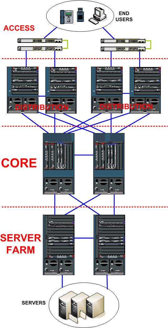
The picture shows the Campus Network building blocks model that is the most common topology in Enterprise Network. It contains Access or Edge Switches where the end users are connected, Distribution Switches as aggregation point for the Access Switches, Core Switches as the central of the network, and Server Farm Switches to connect all the servers.

Why do we need such blocks model? Because it’s modular and scalable. Most of the time we use duplicate hardware and multiple connection links on each block to provide redundancy. Connection to the Internet, through the firewall, can be facilitated by connecting the Internet building block to the Core Switches. And it applies to connection to branch offices as well, called Wide Area Network (WAN), the building block can be connected to Core Switches. I don’t draw both Internet and WAN blocks for the sake of simplicity.

Cisco Systems offers service module on its chassis-based switches. The most common modules that my customers opt to buy are Firewall and Intrusion Prevention System (IPS) blades that are installed on Server Farm Switches to protect the servers. Firewall modules or well known as Firewall blades will be one of the key of implementing MPLS VPN in my scenario.

So what are the requirements? My customers have 8 different users group that are separated into 8 different VLANs. All those VLANs shall communicate to each other without any restrictions except for the 8th VLAN: they must not see the other VLANs at all, but some selective users from different VLANs should be able to establish one-way communication to that 8th VLAN. The 8th VLAN will have its own Internet connection through ADSL, and not through the main Internet link and Internet building block, and it considered to be out of my customer administration control completely. So the main idea is just like having De Militarized Zone (DMZ) inside the internal network separated in different edge switches location!

In normal circumstances, I would configure inter-VLAN routing on the closest Layer 3 Devices to the end users, and put Access Control List (ACL) to provide the restriction. The problem with this approach: administration overhead to maintain the ACL. Any modification on the ACL requires any reconfiguration on all those Layer 3 Devices.

So I chose more elegant way by simply enabling MPLS VPN. Especially since the hardware used in this scenario are Cisco 6500/7600 model with Supervisor 720-3B module that supports MPLS in the hardware.

Following is the step-by-step how I accomplish my goal:

Step 1: Physical Connection
As it showed in the picture, there are multiple links to provide redundancy. Access Switches are connected to 2 different Distribution Switches, each Distribution Switch is connected to both Core Switches and they are connected to each other as well. Server Farms Switches are just like another distribution switches: connected to each other and to both Core Switches. The connection between Distribution – Core – Server Farms is utilizing high speed 10 Gigabit per second fiber links. Connection between Access to Distribution can use 1 Gigabit per second or more with Ether-Channel technology, and it depends on the over-subscription ratio: the ratio between number of end users and the uplink. Access Switches can be stacked, and with the new StackWise technology from Cisco on 3750 series switches, all access switches in 1 stack act as 1 switch with combined number of interfaces.

Step 2: Connectivity with Interior Gateway Protocol (IGP)
The next step is to provide connectivity with IGP Routing. I chose OSPFv2 and put Core, Distribution, and Server Farm Switches into Area 0 Backbone. Connection between Distribution to Access, most of the time it is the Switch Virtual Interface (SVI) or VLAN Interface, is placed into different area to facilitate Summarization into Area 0.

The 2 Firewall blades installed in 2 Server Farm switches are configured in Single Context mode and active-passive failover. We must configure 1 VLAN between Server Farms Switches and the Firewall blades, and this VLAN acts as the “Outside” network for the Firewalls. OSPF Totally Stub Area is configured between 2 Server Farm switches and the active Firewall, to inject only default route to the firewall blade pointing to the switches, and to get the routes to all the Servers networks behind the Firewall blade.

For connection between Distribution to Access, if I terminate Layer 2 VLAN in Distribution Switches with SVI, Distribution Switches will be the routing gateways for all the end users. But if I want to have the same VLAN spans across multiple Access Switch stacks, then I need to run Hot Standby Routing Protocol (HSRP) on both Distribution Switches and I must have Layer 2 Link or Trunk between Distribution Switches. Having layer 2 Trunk between Distribution Switches, and from Distribution to Access switches, can forms Layer 2 loop between Distribution – Access – Distribution and it forces me to rely on Spanning Tree Protocol (STP) to break this loop. Now I have 3 different protocols running in my Distribution Switches: IGP, HSRP, STP and I require to sync the configuration on all those 3 protocols.

I don’t want to get into that complexity, and since my Access switches are Cisco 3750 with EMI software, I decided to run Layer 3 Routing between Distribution and Access. So Access Switches are the gateways for all the end users now. Having Routing to the Access model provides several benefits: there is only 1 protocol for connectivity within the network which is the IGP, we can use Layer 3 tools such as Ping and Traceroute to verify end-to-end connectivity and not bother to check all Layer 2 parameters such as STP root bridge etc, and by default IGP provides equal cost load balancing to utilize better of all the uplinks from the Access to Distribution.

The link from Distribution to Access can use Ether-Channel to provide more than 1 Gbps connection. It’s a Layer 2 Trunk that allows only 1 VLAN to pass through and this VLAN is used as Layer 3 link from Access to Distribution. I can make the Ether-Channel interface as Layer 3 port directly but I would need another Layer 3 link for my MPLS VPN. It will be explained next in Step 4.

Step 3: Enable MPLS LDP on all MPLS-enabled devices

This step is straight forward. By default with current IOS version, Cisco enables Tag Distribution Protocol (TDP) instead of Label Distribution Protocol (LDP). So what I need to do is only defining 1 loopback interfaces as my Router ID and enabling LDP on all interfaces required.

Cisco 3750 access switches don’t support MPLS labeling. So in my scenario the MPLS cloud is formed between Distribution – Core – Server Farms. Core Switches act as P routers and both Distribution and Server Farms Switches act as PE routers.

Quick verification can be done by looking at the LDP neighborship on each MPLS device. Up to this step, we have already had our MPLS backbone ready for the real application: MPLS Layer 3 VPN.

Step 4: Virtual Routing Forwarding (VRF) and PE-CE links
It’s time to enable VRF on each Distribution. Define the Route Distinguisher (RD) and Route Target (RT) and assign the PE-CE links into the VRF. If I chose the Routing to Distribution model, where Distribution Switches are the routing gateways for all end users, the PE-CE links are the SVI interfaces.
But since I decide to have Layer 3 Routing between Distribution and Access, then I need to create another VLAN for Layer 3 link from Distribution to Access. So now I have 2 VLANs for Layer 3 links between Distribution and Access: 1 for the global routing and 1 for the VRF.

Cisco 3750 switch with EMI software supports multi-VRF or VRF-lite feature. Basically with this feature we still can’t do MPLS labeling but it can extend the VRF from Distribution to Access switches. So in any Access switches where I have the 8th VLAN, what I need to do: create the VLAN, assign particular ports into the VLAN, create SVI or VLAN interface as the default gateway for the end users, create VRF with Route Distinguisher, then assign the SVI into the VRF. The same VRF will be assigned to one of the VLAN for layer 3 links to Distribution. Now I have VRF all the way from Distribution, Layer 3 Link between Distribution and Access, and the SVI in Access switches.

Since the 8th VLAN Interface will be part of VRF, the subnet will not show up in global routing table in any Access Switches hence it won’t be able to communicate to any other VLANs even in the same Access switch.

Communication between PE – CE can utilize Static, RIP, OSPFv2, EIGRP and even BGP. If there is only 1 VLAN just like in my scenario, I can use Static Routing for the sake of simplicity. So Distribution will have static route for the 8th VLAN pointing to the Access Switch, and the Access Switch can have Static default route pointing to both Distribution Switches. If I want to use OSPFv2 and on each Distribution it has to run in different Process ID than the OSPFv2 that provides connectivity for global routing.

All the users in 8th VLAN can reach each other within the same Distribution Switches. Now it’s the time to connect them to another Distribution Switches and Server Farms.

Step 5: Multi-Protocol BGP (MP-BGP) and Route Reflectors
MP-BGP is used to transmit the VRF routes from one PE to another PE. The first thing we need to do is to make both Core Switches as BGP Route Reflectors, to avoid having a fully mesh topology. All PEs are required to establish the communication to Route Reflectors only. Remember, with MP-BGP we need to configure Address Family VPNv4 under BGP Routing configuration, activate the neighbors and enable BGP Extended Community to transfer the Route Target parameters. Route Target is used to define with route will be exported and installed on each PE router.

On each Distribution Switch, all Static or OSPFv2 routes that is used in PE-CE connection need to be redistributed into BGP, and all BGP VPNv4 routes achieved from another PE need to be redistributed into the VRF OSPFv2. If we use Static Routing, default gateway has to be configured on each Access Switches pointing to Distribution.

Once we complete this step, all Distribution and Server Farm Switches should be able to see all 8th VLAN routes inside the VRF routing table.

Step 6: Connecting the VPN to the Global Network
Connectivity between 8th VLAN in different Distribution Switches has been achieved, now it’s time to connect this VPN to the rest of the network that I call Global Network. Firewall blade is the key here. It protects all the servers and at the same time it acts as the meeting point between 8th VLAN VRF and the rest of the network.

Between Server Farm Switches and Firewall blades, we have already configured 1 VLAN as the Outside network for the Firewalls. So any traffic to the Servers from all user VLANs, except the 8th VLAN, get into the Firewalls through this Outside network VLAN. Now we need to create another VLAN between Server Farm Switches and Firewall Blades, and assign this VLAN into the VRF. This VLAN will act as DMZ network connected to Firewall Blades.

By default Cisco Firewall modules only allow to have 1 SVI or VLAN interfaces in single context mode to act as Outside interfaces. To circumvent this problem, we need to enable firewall multiple-vlan-interfaces feature. Use this feature with caution! Wrong configuration may lead to the traffic bypassing the Firewalls to reach the servers.

Once we have another VLAN acting as DMZ for the Firewalls, we can setup the Access Control List in the Firewall blades to allow communication from the VPN to the servers, or communication between all other VLANs to the 8th VLAN.

Static routing for traffic to the servers or any other VLANs can be configured in Server Farm Switches VRF pointing to Firewall blades DMZ interface, and this static route must be redistribute into the MP-BGP so all 8th VLANs know how to reach all servers and any other VLANs. We should do the same trick for global network so all other VLANs know how to reach the 8th VLAN through the Firewall blade Outside interface.

Step 7: Network Ready For Use testing
It’s time to verify our setup. We should test the connectivity with step-by-step approach: verify the IGP for global routing, verify MPLS LDP in all MPLS-enabled devices, check the PE-CE connectivity, test the connection between 8th VLAN in different Access Switches but still connected to the same Distribution Switches, verify the VPNv4 routes, and test connectivity between 8th VLAN in different Distribution Switches, and connectivity to the Firewall blade and Server Farms Switches.
The last verification, check the ACL on Firewall blades to make sure 8th VLAN can connect to the servers but not to any other VLANs in global network, and selected users from any other VLANs are allowed to communicate to the 8th VLAN through the Firewalls.


As you can see, one of the benefit of using MPLS Layer 3 VPN instead of distributed ACL on each Distribution Switch is to cut the administration overhead to maintain the network. We can have a single infrastructure to provide different isolated users group or network on top of it, and the policy to control the communication between different users group can be centralized using Firewall Blade.

I’m using MPLS VPN to segregate the 8th VLAN. One day I may come across the requirements to segregate all those 8 VLANs into 8 different isolated networks, and allow the communication between each other only through centralized Firewall. That will be the day I would say Thank You, Once Again to all the guys who invented MPLS Layer 3 VPN.

Wednesday, February 23, 2005

Kismet on WRT54G the Easiest Way

Linksys WRT54G is awesome.
It's an ADSL wireless router with linux-based software inside, licensed under GPL.
The price is reasonable, Amazon sells it for $60. I got mine from local store for about $80. The only drawback with WRT is it's not compatible with ADSL service offered by the only ISP in this country, Etisalat. But you know what? It means your chance to bargain the price is even better!
The most interesting feature from WRT is you can replace the software with third party firmware. Hey, it means we void the warranty! This is acceptable in the world where the only way to find the truth is by hacking. Suck the knowledge by testing and trying. Fill the brain with the answers of uncertainty.

Anyway, today we are going to make Linksys WRT54G as wireless IDS. This ADSL router will become the sensor or drone for famous wireless tool Kismet. As per its website, Kismet is an 802.11 layer2 wireless network detector, sniffer, and intrusion detection system. Kismet identifies networks by passively collecting packets and detecting standard named networks, detecting (and given time, decloaking) hidden networks, and infering the presence of nonbeaconing networks via data traffic.

There are several people that already have mentioned how we can run Kismet on WRT. From Rasmus’ Toys Page, RenderLab, Kismet forum, to Netstumbler discussion forum.
Just remember the following:
- WRT54G is only the drone, the sensor that collects wireless information. We need another computer or notebook running kismet server. Please don't run Micro$oft Window$ even it's possible, and we need to have SSH/SCP client as well
- When running kismet in WRT, we can’t use it as wireless access point at the same time
- All kismet files that we copy to WRT are kept temporarily in /tmp directory, and it will be flushed every time we reboot the device
- By doing this hack, there is a chance to ruin the router, screw the software and turn the device into blue colored brick, nice dual-antenna decoration for your living room … hmm, it’s worth $60, isn’t it?

Now, let's our adventure begins!
1. Read this blog until you understand what you are going to do.
2. If you are new to kismet, try to install it in your notebook and play around a bit to get familiar with the interface and configuration file.
3. Get the third party firmware. I’m using Sveasoft Satori-4.0 version firmware, so if you guys want to follow my steps, download it from Linksysinfo site. You must register but it’s free anyway. Btw, this is the last free version available from Sveasoft. To get the new version (alchemy) you need to donate $20 to them. But hey, $20 is nothing for cool firmware they produce. Unfortunately I can't subscribe since UAE is not in paypal country list.
4. Connect to WRT with your browser. Default IP address is 192.168.1.1, so type http://192.168.1.1 in your browser and put “admin” in password when prompted. You may change the IP address or your password as you wish. My WRT is using 10.1.1.10 IP address.
5. Replace linksys original software by going to Administration, Firmware Upgrade. Click browse and find the firmware, then push upgrade. If you are a religious man, start praying. Hopefully everything fine and you can complete the upgrade.
6. The router will reboot automatically and when it comes back you should see Satori-4.0 in Firmware Version.
7. Now go to Administration, Management and enable SSH.
8. We need to put our public key in Authorized Keys column. Assuming you are using Linux or *BSD with OpenSSH client in your notebook, generate the public-private key pairs:
[root@immortal ~]# ssh-keygen –t rsa

9. Grab the content of your public key from .ssh/id_rsa.pub file, and paste it in WRT's Authorized Keys.
10. Now you can SSH from your notebook to the router without putting any password.
11. Download the pre-compiled kismet drone binary from here. It’s bz2 file so you can decompress it using bz2 –d option, then untar the file by using tar –xvf option to get kismet folder.
12. Kismet folder contains /etc and /bin folder. We need to edit kismet_drone.conf file. In my case, for example, I modified the network in allowed host from default 192.168.0.0/16 to 10.0.0.0/8 network. Kismet server can connect to the drone from anywhere, as long as it still in “allowed host” scope. Btw, if you don’t know the meaning of /16 or /8, RTFM!
I assume my WRT54G is v2, since I don’t need to modify the source in kismet drone configuration file: source=wrt54g,eth1,wrt54g
13. Now we can upload the whole kismet folder to our WRT using scp:
[root@immortal ~]#scp –r kismet root@10.1.1.10:/tmp/kismet

Don’t forget to change the IP address according to your router address.
14. SSH to your WRT, and run the kismet drone:
(none):[~]# /tmp/kismet/bin/kismet_drone
Suid priv-dropping disabled. This may not be secure.
No specific sources given to be enabled, all will be enabled.
Enabling channel hopping.
Disabling channel splitting.
Source 0 (wrt54g): Enabling monitor mode for wrt54g source interface eth1 channel 6...
Source 0 (wrt54g): Opening wrt54g source interface eth1...
Kismet Drone 2004.04.devel_nikki_2004.05.23 (Kismet)
Listening on port 3501 (protocol 8).
Allowing connections from 10.0.0.0/255.0.0.0
WARNING: Setting driver in STA mode to enable channel hopping

Yes, it’s on, baby! Kismet drone is running and ready to accept the connection from kismet server on port 3501.
15. You need to run kismet server in your notebook. If you haven’t installed it, do so by compiling from source or type “emerge kismet” for Gentoo users.
We have to modify the kismet configuration file, /etc/kismet.conf by default, to use kismet drone as source:
source=kismet_drone,10.1.1.10:3501,drone

If you like kismet server to drop the privilege to normal user, put the username in suiduser configuration: suiduser=himawan

16. Change your working directory to any directory where the user that you specified in suiduser can write the kismet log files, then start kismet as root:
[root@immortal tmp]# kismet

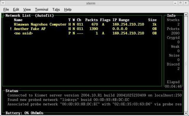
If everything’s ok, you should get the kismet panel interface just like below:


Well, it’s not difficult, isn’t it?
Just remember, every time you reboot WRT, you have to upload the kismet directory again using SCP.

Now what?
To make WRT54G running as real IDS, we have to analyze the log files in kismet server. Kismet will dump the wireless traffic its captured to Kismet-date.dump file. Then we can read the file using tcpdump –r option or ethereal. Or maybe test the traffic against snort rules?
I’ll check this later on. Now what I have in my mind is to use this router to do …
WARDRIVING!

Thursday, February 10, 2005

PIX Firewall-ing (Part 3)

To allow people from the Internet to connect to the servers located inside our internal network, we need to do 3 steps:
1. Create a static translation between one public IP address to the real IP address of our servers
2. Create an access control list to allow access to the server public IP address
3. Apply the access list on the interface

Suppose we have a web server with real IP address 192.168.1.5. This server will be translated to public IP address 1.1.1.5.
First, we have to create static translation with static command:
pixfirewall(config)#static (inside,outside) 1.1.1.5 192.168.1.5

The format of the command is: static (higher security interface,lower security interface) public_IP_address internal_IP_address
To verify the translation is correct we can use 'show xlate' command:
pixfirewall(config)#show xlate
Global 1.1.1.5 Local 192.168.1.5

Now we need to create access control list. Access control list is a rule set for any traffic allowed or not allowed to particular destination. PIX uses 'default deny' concept, it means it you don't permit it explicitly in the rule set, the traffic will be denied.
The format is: access-list name_of_the_ruleset permit/deny protocol source destination eq ports. Protocol can be TCP, UDP, ICMP or even IP protocol such as ESP etc. If we don't specify any ports, it means we allow any ports for that protocol.
In this case, we want to allow access to our web server from anywhere on the Internet with destination port is port 80 or HTTP.
pixfirewall(config)#access-list externalrule permit tcp any host 192.168.1.5 eq 80

Remember, the destination IP address is the public IP of the web server, and not the real IP. Suppose we have 1 network 192.168.1.0/24 full of web servers (what kind of network is that?) and we want to allow anyone to connect to those all servers using HTTP:
pixfirewall(config)#access-list externalrule permit tcp any 192.168.1.0 255.255.255.0 eq 80

To apply the access-list on the interface, type the following:
pixfirewall(config)#access-group externalrule in interface outside

Until PIX OS 6.2, the access list can have only one direction, “in” means traffic flowing into interface outside from Internet. Consider yourself as firewall, you have one interface called outside, and any traffic coming to you from that interface will be inspected using access list named externalrule.

Ok, so now Internal network can go to the Internet and people from the Internet can connect to our web server using HTTP protocol.
What's next?
Let's put the name for the firewall:
pixfirewall(config)#hostname kungfuzen
kungfuzen(config)#

We need to put the password to connect to PIX remotely and enable the password to switch from user mode to privilege mode:
kungfuzen(config)#passwd password_for_telnet_or_ssh
kungfuzen(config)#enable password password_to_switch_to_priv_mode

PIX can be managed remotely by telnet or SSH from trusted interface. PIX can be managed only by SSH from outside interface. To enable SSH, we need to specify the domain name and generate key first:
kungfuzen(config)#domain-name pixsucks.com
kungfuzen(config)#ca generate rsa key 2048
For >= 1024, key generation could
take up to several minutes. Please wait.

Where 2048 is the key modules size. Save the key with following command:
kungfuzen(config)#ca save all

Then specify from where you can connect to PIX
kungfuzen(config)#ssh 0.0.0.0 0.0.0.0 inside
kungfuzen(config)#ssh 1.1.1.1 255.255.255.255 outside

PIX uses SSH version 1 and user name 'pix' so to connect from SSH client in *nix from inside, use this command:
[user@unix ~]$ ssh -l pix -c DES 192.168.1.1
pix@192.168.1.1's password:

Use the password as what we set with 'passwd' command. You will get the user mode prompt. Switch to privilege mode by typing 'enable' and put the password as what we specify using 'enable password'.

I think this will be the end of my PIX Firewall tutorial. There are so many features left in PIX that you can explore by yourself: application inspection using fixup, HTTP authentication, VPN, IDS feature, turbo access list. flood guard, failover etc. This link will take you to Cisco documentation for Cisco PIX 6.3.
Come on, you guys are grown-up, so I don't think I need to explain all Cisco PIX commands here. Just RTFM and use '?” anytime you are in doubt. Cisco website and google are your friends. Try all 'show' commands to check the status or the configuration.

In case this firewall doesn't belong to you, just erase the configuration completely by typing:
kungfuzen#write erase

Reboot the PIX, and.. voila! Back to factory default.
Now, put firewall back inside the box, wrap it, sell it in eBay or deliver the box to the real owner. As you wish. Good day.

Wednesday, February 09, 2005

PIX Firewall-ing (Part 2)

Now to configure PIX we need to go to configuration mode. Type 'enable' from user mode prompt to get privilege mode prompt (#).
pixfirewall>enable
pixfirewall#

In privilege mode, we still can't modify the configuration but we can upgrade the software, reload, and run some debug for troubleshooting. Since this is a new firewall, there is no password to switch from user mode to privilege mode.

Now let's go to configuration mode, by typing 'configure terminal'
pixfirewall#conf t
pixfirewall(config)#

In PIX, you don't have to type the complete command. As long as the word we type is unique pointing to only one command, PIX will accept the command.
Firewall_name(config)# is global configuration mode prompt where normally in Cisco IOS we can configure only parameters that affect the device globally. For example, in Cisco router, in global mode we configure the name of the device. And to configure the IP address for one interface, you must go to that interface configuration mode and get the router(config-if)# prompt.
But this is not the case with PIX, global config mode is the only mode available to configure the firewall.

By default the interfaces are disable, so let's enable them:
pixfirewall(config)#interface ethernet0 auto
pixfirewall(config)#interface ethernet1 auto

Auto means the interface will negotiate the hardware speed automatically with the hub/switch where it's connected to.

Let's give the IP address to the interface, accordingly to the external network and internal network, using interface alias name:
pixfirewall(config)#ip address outside 1.1.1.2 255.255.255.0
pixfirewall(config)#ip address inside 192.168.1.1 255.255.255.0

All hosts in internal network need to use PIX inside interface IP address as default gateway. PIX itself needs to know its default gateway to send the traffic to external network or Internet, so let's specify the gateway (for example, Internet router ethernet IP address):
pixfirewall(config)#route outside 0.0.0.0 0.0.0.0 1.1.1.1

Now, unless we are freaks who have enough public IP for Internal network, I assume we use private IP so we need to NAT them to be able to go to the Internet.pixfirewall(config)#nat (inside) 1 0 0
pixfirewall(config)#global (outside) 1 1.1.1.3

How to read 'nat' command: any network behind interface inside (0 0 means 0.0.0.0 0.0.0.0) will be translated based on rule number '1' in any interfaces set with 'global'
How to read 'global' command: in interface outside, set translation rule number '1' so any network NAT-ed with this rule will be translated as 1.1.1.3 IP address.

We can also use PIX firewall outside interface IP address as translation IP.
pixfirewall(config)#global (outside) 1 interface

It means: inside network (in this case 192.168.1.0/24) will be translated to interface outside IP address (1.1.1.2) when they try to go to the Internet.
We can also use range of public IP address to translate internal network:
pixfirewall(config)#global (outside) 1 1.1.1.10-1.1.1.20

You know what?
That's the only configuration you need to connect your internal network to the Internet. Just try to connect one PC on internal network, give IP address and default gateway accordingly, and this PC should be able to go to the Internet. Obviously you need to have Internet line and proper DNS setting but I won't discuss it because you are so lame if you don't know this!

With this minimal configuration, your internal network should be able to go to the Internet without any restriction and from the Internet no one should be able to connect to you.

Don't forget to save the configuration to make sure it will be available even if we reboot the firewall, by typing 'write memory' or 'wr m' for short:
pixfirewall#wr m

You can save the configuration from global mode or privilege mode, but not from user mode (> prompt). By the way, to go back to privilege mode from global mode just type 'exit'. To go back to user mode from privilege mode, type 'disable' since typing 'exit' from privilege mode will log you out from PIX.

As summary, 6 steps you need to do to be able to connect your internal network to the Internet and protected by PIX firewall:
1. Enable the interfaces
2. Give IP address for all interfaces
3. Put default route to outside network, pointing to Internet router ethernet interface for example
4. Put NAT in interface inside with translation rule number
5. Put Global in interface outside matching the translation rule number and the public IP address, can use PIX outside interface IP address or range public IP address
6. Save the configuration

How about if we want people from the Internet connect to our servers inside the Internal network?

(To be continued in part 3)

PIX Firewall-ing (Part 1)

Cisco PIX Firewall is one of the best commercial firewall in the world. Pay attention to the word 'commercial'. I'm not comparing this expensive appliance with my love PF or even IP Tables, those two are free and powerful too! But like it or not, in the world where companies trust branded products and vendors, Cisco PIX really kicks in the firewall market.

Being an appliance means PIX has its own underlying operating system. And this is one of its advantage. Close-source is an evil, but for PIX it means no service running as default. And less people know about the PIX underlying OS means script kiddies with full of exploits for multi-purpose OS need to work hard to find specific exploit for PIX.
It doesn't mean PIX doesn't have any vulnerabilities. On November 2002, for example, Cisco announced the vulnerability in ISAKMP and HTTP authentication. Not running default services doesn't mean you don't want to enable them for your requirement, right?

Anyway, I'm not here to curse PIX. I'm a CCIE, remember? And I make money by selling Cisco products.
Today I'm going to explain how to make PIX firewall up and running in few minutes. But before we start, there are some concepts need to be noted:

PIX firewall is a stateful firewall, it means PIX tracks the TCP and UDP conversation. Different with PF where we have to put 'keep state' keyword, PIX does this automatically without additional configuration.

PIX distinguishes its interfaces by putting parameter called security levels.
For example, in PIX 506E
with two interfaces, by default it has already put the alias name for those interfaces as 'outside' and 'inside'. As per their name, outside interface should be used to connect to outside the internal network (for example Internet), and inside interface should be connected to internal network we want to protect.

Interface outside has security level 0 (lowest trusted) and interface inside has security level 100 (highest trusted).
Traffic coming from the network connected to interface with higher security level can flow without any restrictions to the network connected to interface with lower security level. In contrary, traffic coming from the network connected to interface with lower security level, can't flow to the network connected to interface with higher security level, unless we permit it explicitly using Access Control List.

Using default configuration, internal network should be able to go to outside network or Internet, and traffic from outside network or Internet should not be able to go into the internal network unless we explicitly put the access control list.
If PIX has more than 2 interfaces, the other interfaces can have security level between 0 to 100, and the same rule implies.

Enough talking, let's configure one Cisco PIX506E. This is one of the cheapest Cisco PIX firewall available that can have only 2 interfaces maximum. You need to get Cisco PIX for sure. I'm not interested to hear from where you get it, just open it from the box and switch it on.

After we boot our brand new PIX, we'll end up with “(firewall_name)>” prompt. This is what Cisco called as user mode prompt. The command we can execute is limited, just type “?” to see available commands.

(By the way, I assume you guys a bit familiar with basic Cisco command and OS. To connect to brand new Cisco devices without configuration, you must use cisco console cable, roll-over cable with serial port in one end and RJ45 normal ethernet plug on the other end. So connect the serial port to your PC com port, and the RJ45 port to 'console' port in Cisco. Then use serial console terminal such as Hyper Terminal in Window$, or minicom, tip, zmodem etc in *nix. Just remember to set the speed to 9600.)

The first thing we need to do is checking the hardware capabilities using “show version” command.
pixfirewall>show version

From show version output, we can get following information:
- PIX OS Version number
- PIX Device Manager (Web based administration tool) version number
- System uptime
- Hardware information such as CPU and flash drive size... see, PIX 506 is only a crap Pentium II 300 Mhz and 32 Mb RAM. So much for a thousand bucks, huh?
- Number of interfaces and interfaces name
- Licensed feature such as failover, encryption for VPN (DES/3DES), how many maximum interfaces total we can have
- Serial number, needed to generate Activation key
- Running activation key
- Last modified configuration, when and by whom

Remember, PIX is commercial product that works on license, so if you don't see any feature you need (such as 3DES or failover), then you need to buy upgrade license and generate new activation key using the serial number of the firewall.

(To be continued in part 2)