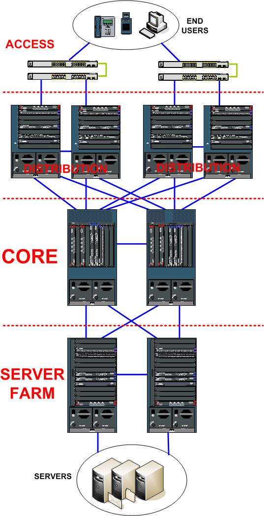
 The picture shows the Campus Network building blocks model that is the most common topology in Enterprise Network. It contains Access or Edge Switches where the end users are connected, Distribution Switches as aggregation point for the Access Switches, Core Switches as the central of the network, and Server Farm Switches to connect all the servers.
Why do we need such blocks model? Because it’s modular and scalable. Most of the time we use duplicate hardware and multiple connection links on each block to provide redundancy. Connection to the Internet, through the firewall, can be facilitated by connecting the Internet building block to the Core Switches. And it applies to connection to branch offices as well, called Wide Area Network (WAN), the building block can be connected to Core Switches. I don’t draw both Internet and WAN blocks for the sake of simplicity.
Cisco Systems offers service module on its chassis-based switches. The most common modules that my customers opt to buy are Firewall and Intrusion Prevention System (IPS) blades that are installed on Server Farm Switches to protect the servers. Firewall modules or well known as Firewall blades will be one of the key of implementing MPLS VPN in my scenario.
So what are the requirements? My customers have 8 different users group that are separated into 8 different VLANs. All those VLANs shall communicate to each other without any restrictions except for the 8th VLAN: they must not see the other VLANs at all, but some selective users from different VLANs should be able to establish one-way communication to that 8th VLAN. The 8th VLAN will have its own Internet connection through ADSL, and not through the main Internet link and Internet building block, and it considered to be out of my customer administration control completely. So the main idea is just like having De Militarized Zone (DMZ) inside the internal network separated in different edge switches location!
In normal circumstances, I would configure inter-VLAN routing on the closest Layer 3 Devices to the end users, and put Access Control List (ACL) to provide the restriction. The problem with this approach: administration overhead to maintain the ACL. Any modification on the ACL requires any reconfiguration on all those Layer 3 Devices.
So I chose more elegant way by simply enabling MPLS VPN. Especially since the hardware used in this scenario are Cisco 6500/7600 model with Supervisor 720-3B module that supports MPLS in the hardware.
Following is the step-by-step how I accomplish my goal:
Step 1: Physical Connection
As it showed in the picture, there are multiple links to provide redundancy. Access Switches are connected to 2 different Distribution Switches, each Distribution Switch is connected to both Core Switches and they are connected to each other as well. Server Farms Switches are just like another distribution switches: connected to each other and to both Core Switches. The connection between Distribution – Core – Server Farms is utilizing high speed 10 Gigabit per second fiber links. Connection between Access to Distribution can use 1 Gigabit per second or more with Ether-Channel technology, and it depends on the over-subscription ratio: the ratio between number of end users and the uplink. Access Switches can be stacked, and with the new StackWise technology from Cisco on 3750 series switches, all access switches in 1 stack act as 1 switch with combined number of interfaces.
Step 2: Connectivity with Interior Gateway Protocol (IGP)
The next step is to provide connectivity with IGP Routing. I chose OSPFv2 and put Core, Distribution, and Server Farm Switches into Area 0 Backbone. Connection between Distribution to Access, most of the time it is the Switch Virtual Interface (SVI) or VLAN Interface, is placed into different area to facilitate Summarization into Area 0.
The 2 Firewall blades installed in 2 Server Farm switches are configured in Single Context mode and active-passive failover. We must configure 1 VLAN between Server Farms Switches and the Firewall blades, and this VLAN acts as the “Outside” network for the Firewalls. OSPF Totally Stub Area is configured between 2 Server Farm switches and the active Firewall, to inject only default route to the firewall blade pointing to the switches, and to get the routes to all the Servers networks behind the Firewall blade.
For connection between Distribution to Access, if I terminate Layer 2 VLAN in Distribution Switches with SVI, Distribution Switches will be the routing gateways for all the end users. But if I want to have the same VLAN spans across multiple Access Switch stacks, then I need to run Hot Standby Routing Protocol (HSRP) on both Distribution Switches and I must have Layer 2 Link or Trunk between Distribution Switches. Having layer 2 Trunk between Distribution Switches, and from Distribution to Access switches, can forms Layer 2 loop between Distribution – Access – Distribution and it forces me to rely on Spanning Tree Protocol (STP) to break this loop. Now I have 3 different protocols running in my Distribution Switches: IGP, HSRP, STP and I require to sync the configuration on all those 3 protocols.
I don’t want to get into that complexity, and since my Access switches are Cisco 3750 with EMI software, I decided to run Layer 3 Routing between Distribution and Access. So Access Switches are the gateways for all the end users now. Having Routing to the Access model provides several benefits: there is only 1 protocol for connectivity within the network which is the IGP, we can use Layer 3 tools such as Ping and Traceroute to verify end-to-end connectivity and not bother to check all Layer 2 parameters such as STP root bridge etc, and by default IGP provides equal cost load balancing to utilize better of all the uplinks from the Access to Distribution.
The link from Distribution to Access can use Ether-Channel to provide more than 1 Gbps connection. It’s a Layer 2 Trunk that allows only 1 VLAN to pass through and this VLAN is used as Layer 3 link from Access to Distribution. I can make the Ether-Channel interface as Layer 3 port directly but I would need another Layer 3 link for my MPLS VPN. It will be explained next in Step 4.
Step 3: Enable MPLS LDP on all MPLS-enabled devices
This step is straight forward. By default with current IOS version, Cisco enables Tag Distribution Protocol (TDP) instead of Label Distribution Protocol (LDP). So what I need to do is only defining 1 loopback interfaces as my Router ID and enabling LDP on all interfaces required.
Cisco 3750 access switches don’t support MPLS labeling. So in my scenario the MPLS cloud is formed between Distribution – Core – Server Farms. Core Switches act as P routers and both Distribution and Server Farms Switches act as PE routers.
Quick verification can be done by looking at the LDP neighborship on each MPLS device. Up to this step, we have already had our MPLS backbone ready for the real application: MPLS Layer 3 VPN.
Step 4: Virtual Routing Forwarding (VRF) and PE-CE links
It’s time to enable VRF on each Distribution. Define the Route Distinguisher (RD) and Route Target (RT) and assign the PE-CE links into the VRF. If I chose the Routing to Distribution model, where Distribution Switches are the routing gateways for all end users, the PE-CE links are the SVI interfaces.
But since I decide to have Layer 3 Routing between Distribution and Access, then I need to create another VLAN for Layer 3 link from Distribution to Access. So now I have 2 VLANs for Layer 3 links between Distribution and Access: 1 for the global routing and 1 for the VRF.
Cisco 3750 switch with EMI software supports multi-VRF or VRF-lite feature. Basically with this feature we still can’t do MPLS labeling but it can extend the VRF from Distribution to Access switches. So in any Access switches where I have the 8th VLAN, what I need to do: create the VLAN, assign particular ports into the VLAN, create SVI or VLAN interface as the default gateway for the end users, create VRF with Route Distinguisher, then assign the SVI into the VRF. The same VRF will be assigned to one of the VLAN for layer 3 links to Distribution. Now I have VRF all the way from Distribution, Layer 3 Link between Distribution and Access, and the SVI in Access switches.
Since the 8th VLAN Interface will be part of VRF, the subnet will not show up in global routing table in any Access Switches hence it won’t be able to communicate to any other VLANs even in the same Access switch.
Communication between PE – CE can utilize Static, RIP, OSPFv2, EIGRP and even BGP. If there is only 1 VLAN just like in my scenario, I can use Static Routing for the sake of simplicity. So Distribution will have static route for the 8th VLAN pointing to the Access Switch, and the Access Switch can have Static default route pointing to both Distribution Switches. If I want to use OSPFv2 and on each Distribution it has to run in different Process ID than the OSPFv2 that provides connectivity for global routing.
All the users in 8th VLAN can reach each other within the same Distribution Switches. Now it’s the time to connect them to another Distribution Switches and Server Farms.
Step 5: Multi-Protocol BGP (MP-BGP) and Route Reflectors
MP-BGP is used to transmit the VRF routes from one PE to another PE. The first thing we need to do is to make both Core Switches as BGP Route Reflectors, to avoid having a fully mesh topology. All PEs are required to establish the communication to Route Reflectors only. Remember, with MP-BGP we need to configure Address Family VPNv4 under BGP Routing configuration, activate the neighbors and enable BGP Extended Community to transfer the Route Target parameters. Route Target is used to define with route will be exported and installed on each PE router.
On each Distribution Switch, all Static or OSPFv2 routes that is used in PE-CE connection need to be redistributed into BGP, and all BGP VPNv4 routes achieved from another PE need to be redistributed into the VRF OSPFv2. If we use Static Routing, default gateway has to be configured on each Access Switches pointing to Distribution.
Once we complete this step, all Distribution and Server Farm Switches should be able to see all 8th VLAN routes inside the VRF routing table.
Step 6: Connecting the VPN to the Global Network
Connectivity between 8th VLAN in different Distribution Switches has been achieved, now it’s time to connect this VPN to the rest of the network that I call Global Network. Firewall blade is the key here. It protects all the servers and at the same time it acts as the meeting point between 8th VLAN VRF and the rest of the network.
Between Server Farm Switches and Firewall blades, we have already configured 1 VLAN as the Outside network for the Firewalls. So any traffic to the Servers from all user VLANs, except the 8th VLAN, get into the Firewalls through this Outside network VLAN. Now we need to create another VLAN between Server Farm Switches and Firewall Blades, and assign this VLAN into the VRF. This VLAN will act as DMZ network connected to Firewall Blades.
By default Cisco Firewall modules only allow to have 1 SVI or VLAN interfaces in single context mode to act as Outside interfaces. To circumvent this problem, we need to enable firewall multiple-vlan-interfaces feature. Use this feature with caution! Wrong configuration may lead to the traffic bypassing the Firewalls to reach the servers.
Once we have another VLAN acting as DMZ for the Firewalls, we can setup the Access Control List in the Firewall blades to allow communication from the VPN to the servers, or communication between all other VLANs to the 8th VLAN.
Static routing for traffic to the servers or any other VLANs can be configured in Server Farm Switches VRF pointing to Firewall blades DMZ interface, and this static route must be redistribute into the MP-BGP so all 8th VLANs know how to reach all servers and any other VLANs. We should do the same trick for global network so all other VLANs know how to reach the 8th VLAN through the Firewall blade Outside interface.
Step 7: Network Ready For Use testing
It’s time to verify our setup. We should test the connectivity with step-by-step approach: verify the IGP for global routing, verify MPLS LDP in all MPLS-enabled devices, check the PE-CE connectivity, test the connection between 8th VLAN in different Access Switches but still connected to the same Distribution Switches, verify the VPNv4 routes, and test connectivity between 8th VLAN in different Distribution Switches, and connectivity to the Firewall blade and Server Farms Switches.
The last verification, check the ACL on Firewall blades to make sure 8th VLAN can connect to the servers but not to any other VLANs in global network, and selected users from any other VLANs are allowed to communicate to the 8th VLAN through the Firewalls.
As you can see, one of the benefit of using MPLS Layer 3 VPN instead of distributed ACL on each Distribution Switch is to cut the administration overhead to maintain the network. We can have a single infrastructure to provide different isolated users group or network on top of it, and the policy to control the communication between different users group can be centralized using Firewall Blade.
I’m using MPLS VPN to segregate the 8th VLAN. One day I may come across the requirements to segregate all those 8 VLANs into 8 different isolated networks, and allow the communication between each other only through centralized Firewall. That will be the day I would say Thank You, Once Again to all the guys who invented MPLS Layer 3 VPN.
11 comments:
Your posting is very informative! Thanks to you, I would to propose to the solution to my customers.
Hi!
really informative
question, what about beyond that site...how would you communicate between your WAN Router to the provider? and back to your remote router?
email address nme2nme@gmail.com
thanks for the help!
Hi, this MPLS VPN is to segregate VLAN within the LAN. From LAN to the WAN router will pass through the firewall and it depends on the routing between the WAN router - firewall. So communication between WAN router to the provider depends on the WAN link, and from provider's perspective it's transparent, they see the customer as normal LAN. If it's only 1 WAN link then it may use even only static route.
how can lcheck my mpls connectivity speed
It will constrain programs to their own address spaces and provide the basis for a virtual private network (vpn) as standard. Last week, I was reflecting on the vulnerability of widely used operating systems to malicious...
whats happens when the same VLAN spans across multiple Access Switch stacks ? how does layer2 adjacency happen?
hi swap, I have mentioned that if I decided to use "routing to the access" concept so it means the access switch is the IP gateway for the VLANs. In my scenario I can do it that way since the customer assigned unique VLANs on each access switch stack, based on the location.
But even let's say you use the distribution switch as the gateway, the MPLS VPN can still be applied. The routing to the access concept was there to eliminate the requirement to run STP. And since MPLS starts in distribution, while the IP gateway is in access, that's way I need to use multi-VRF or VRF-lite feature so even in a single access switch between different VLANs they can't communicate to each other because they are in a different VPN/VRF
Himwan,
So link between distribution and access is multivrf link right (Multiple subinterfaces between ACCESS and DISTRIBUTION swtich depends on number of VLAN we need to isolate)? and communication between different VLAN will be done via Distribution device right?
I have questions for you. I wish you get to answer them. What will happen when the same VLAN spans across multiple Access Switch stacks? And how does layer2 adjacency take effect? I am really confused with this system.
vpn
Thanks for your post.Your post is very informative.
Post a Comment