Showing posts with label Cisco. Show all posts

Thursday, August 11, 2011

This Time for Africa

I'm currently in Dubai. For only few days before going back to Hungary.

I've just had my first Telepresence meeting with my new team. This is my 6th team since I joined Cisco Systems about 5 years ago. As part of the re-organization within Cisco now I'm with the Service Provider team that focuses on customers in Africa.

Last time I checked, I haven't put any pin in Africa countries yet. I did some project for Bostwana Telecom, but it was done remotely.


    So it's time for Africa.

    But I need to finish my current work in Europe first.

    Sunday, August 07, 2011

    No Competition

    "There is no real friend. There is no real competition. It's only real interest."

    I heard that quote more than 10 years ago. While so far I have proved that there is real friend indeed, I'm yet to see if the theory of no competition can be proved wrong too.

    Well, I think Google is trying to do that now.

    I have seen two companies, that are used to compete to each other, become partner. Or one eventually gets acquired by its competitor. Sometimes two companies are still competing in one area but partnering in some other area.

    Few days ago I saw this news about several Juniper sales executives landed (back) to Cisco. Imagine those who are used to compete with them, now will have them on board in the team.

    There is no real competition?

    And what does it tell us, the individual working as professional?

    I'd say we have to defend our product and to compete to win. I've never met anyone who wants to work in a company that doesn't want to win the competition. But always try to keep the competition healthy. Just prove why we are better and never be rude to the folk who works on the other side. Because you never know, someday he or she may switch to our team. Or you may have chance to switch, and you'd probably want to do that to see how does it feels to be on the other side.

    Google should've known better.

    Thursday, June 04, 2009

    Video Kills the Radio Star

    Jack Black in School of Rock once said, one great rock show can change the world! I guess the same principle applies for networking industry: one great product can really change the world.

    When Cisco Systems developed the first commercial router for public use, it was intended to serve multiple protocols. There was no intention to split the products for a different segment, for example between Service Provider and Enterprise network. The result at that time was a full line of products without clear separation in the products specification between a different market segment. They were all running the same legacy IOS and every product can support the full set of features whether it is required or not.

    Thankfully Cisco realized that there is no one product to serve all. A classified project was started at the end of the 90's to come up with the next generation router with the new hardware architecture and the new software. When Cisco CRS-1 was unveiled in May 2004, it can be seen clearly that this product is the answer of the requirements from service providers to have a robust, high performance and scalable core router. And the product that just celebrated its five year anniversary last month continues to beat the expectation and currently has been deployed in more than 300 providers in the world.

    So once you have a successful product, what's next? Try to replicate the success story and the technology for another products, obviously. The proven hardware architecture and the new true-modular IOS XR have been re-used in other products including the new release Cisco ASR9000 series. I'm very excited about this product because not only Cisco was able to release it during global financial crisis time (there are few products that have been developed for years but must be canceled due to the crisis, and we may need to wait until the financial situation recovers for new inovation) but ASR9000 comes with the similar hardware architecture with CRS-1 that has been proven in many production networks.

    Enough with the history lesson, here comes the main point of my writing today.

    As we all know the demand of Video services has become the main factor of so many technology developments. We live in High Definition era where even DVD quality is not enough. And we all want the video to be delivered to our TV at home through the network. We used to be grateful to YouTube, but now we want more. We ask for higher quality. We want for a full movie. We want to be in control of when and where we want to watch the movie. It has to be available anytime, anywhere, as long as we are connected to the network.

    This means we need a high performance network infrastructure to deliver the video services. We need to ensure the digital packets of the video can be switched as fast as possible. We need more storage to keep all the videos. And not to forget the Video traffic must compete with other type of traffic in the network. This means the Quality of Services must be enforced for different type of network traffic to guarantee the services.

    The Buggles were not wrong when they said Video Killed the Radio Star. But these days Video also kills our bandwidth, chokes our routers, and fills up our storage quickly. And Cisco is the leading company that has a complete line of products that are proven to deliver the Video service end-to-end.

    While other companies are still busy marketing how fast they can bring new independent features to the market, Cisco has done more. They not only can cover all the required products to build a complete solution, they also show how to do it with a proven test result conducted by third-party testing vendor.


    Light Reading and EANTC just released a report yesterday on how they test the Cisco's IP Video Services Delivery network. The tests covered the high availability with sub-second failover time for all network services, in-line video quality monitoring, massive scalability of IP video services and storage area network solutions and virtualization. The products involved are Cisco CRS-1, ASR9000, Cisco 7600-S, and Nexus.

    In summary, Cisco’s IP Video solution showed excellent results:

    - 8,188 multicast groups were replicated across 240 egress ports in a point of presence (PoP), showing that Cisco could serve 1.96 million IP video subscribers in a single metro PoP
    - Accurate in-line video monitoring was demonstrated for video distribution and contribution over IP
    - Sub-50 millisecond failover and recovery times were shown for video distribution and secondary distribution networks using, for the first time in a public test of Cisco equipment, point-to-multipoint RSVP-TE
    - No video quality degradation in the face of realistic packet loss in the network
    - Excellent quality of service (QoS) enforcement in Cisco’s new ASR 9010 router for both fabric oversubscription and head-of-line blocking
    - Hitless control plane failover for converged network

    As I said once, TV is evil. But on-demand TV is not. Simply because now we are in control of our TV.

    Take control your TV. Take control your life.

    Monday, April 20, 2009

    Just Another Day @ Work

    I woke up after only 2 hours sleep. There was no time for taking shower nor breakfast. Still wearing the same short I opened the IP/MPLS Core Low Level Design document that I have just completed several hours before. The design was based on extensive online meetings and conference calls with the customer and my team mates. I applied best practices and optimal design to ensure it has answered all the customer requirements. My presentation slides were ready. I read both documents for the last time just to ensure I didn’t misspell anything.

    I grabbed a Red Bull from the fridge. My laptop was still connected to my company using a secure and encrypted connection. I’ve been spending my time every night until 5 or 6 in the morning for about a month to complete the design. I usually worked on the document in my own bedroom. It gave me a pleasant feeling and put me close with my family. I started working on it after they went to bed, because in a day I would be busy with all the relocation issues and helping my wife to take care of the kids. And working at night from my place would match the time with the folks in US due to a different timezone. My internal company's Instant Messaging system was ready and still blinking as I received the answer to all my queries related to the hardware in the design from the developers in San Jose.

    All the hard work was done, and today was the presentation day.

    I finished up the energy drink that has been keeping me awake for the past several weeks. I login to the WebEx to prepare the session. I fired up the WebEx Connect to ensure I have uploaded all the documents and to check if my team mate puts his latest review of the design there. I used the callback function to dial my IP phone, which I put it on speaker so I could talk at the same time sharing my slides or drawing something on the application that I shared on WebEx. I could share my desktop so the customer can connect to the internal lab from my PC to verify the configuration of the devices that I used to simulate the design. I also wanted to show my face to the customer on the camera while presenting, but after only 2 hours sleep and no shower I would guess it might not be in their best interest to see me.

    I sent message to my mate using IM to check if he was able to see my slides on WebEx. In a few minutes, the other parties would come and join us.

    I was presenting the Low Level Design from my bedroom in Dubai to the customer somewhere in Africa. My team mates were in Spain and Hungary. The Project Manager was sitting at her home in Nigeria.

    Some people say this is how to work in Internet era. Some people call it true Collaboration. Some would say this is how all the web-based collaboration tools leverage the Web 2.0 concept. Others name this as Work 2.0.

    But for me, it was just another day at work.

    Saturday, March 07, 2009

    Deep Diving Router Architecture, Part III

    In the previous two parts we have discussed a lot about the hardware architecture. So where do we go from here? Let’s now discuss the features and the applications running on top of the hardware architecture that we have been discussing so far. I’m running out of the pictures that are available and can be found in google to explain this topic. And obviously I can’t use the picture from my company’s internal document. So let this part be the picture-less discussion.

    The following are few sample features and applications that are required from a modern and next generation router:

    High Availability (HA) and Fast Convergence
    Router fails eventually. The failure may happen on the route processor module, the power supply, the switch fabric, the line card, or the whole chassis somehow. The key point here is not on how to avoid the failure, but how to manage during the failure to minimize time required to switch the traffic to redundant path or module.

    For most of us who like to see a network as a collection of nodes connected to each other, the failure might be only in either link or node failure. For these two cases, router vendors have been introducing Fast Convergence (FC) features in the product such as IGP FC and MPLS TE Fast Re-Route (FRR) to reduce the network convergence time to minimal. And the key point for this type of failure is to detect the failure as soon as possible. If the nodes are connected with direct link, the Loss of Signal (LoS) may be used to inform the failure to the upper layer protocol such as IGP. If it is not direct link, we may use a feature called Bidirectional Forwarding Detection (BFD) which basically sends hello packet from one end to the other.

    When the hardware fails, we expect to see packet loss for fragment of time. In most cases this is inevitable and the only thing we can do is to minimize the packet loss or to reduce the convergence time. For a router with redundant route processor, let’s say the primary route processor fails and it has to switch over to the secondary route processor, it can use a feature called Non-Stop Forwarding (NSF) during the switch over time until the secondary route processor is ready to completely take over, to avoid any packet loss. NSF offers some degree of transparency, since the failure node can inform its neighbors that it’s going to down :) but make promises it will go back online again so please all neighbors don’t flush the routes from the routing table for certain period of time, and please keep forwarding the traffic to the failure node.

    The failure node itself must use modular concept as explained in previous discussion. So the forwarding plane should be done in other location but the route processor, for example in the line cards. Before the failure, the router must run the Stateful Switchover (SSO) feature to ensure the redundant route processor is synchronized with the primary route processor, fabric and the line card. During the switch over, while waiting for initialization process of the secondary route processor to take over completely, forwarding packet is still done in the line card by using the last state of local forwarding table before the failure. So if the failure node can still forwarding the packet to the neighbors, even it uses the last forwarding table state before failure, and the neighbors are willing to continue forwarding the packet to the failure node because they have been informed it will go back online again soon, then we should not have any packet loss at all. Later the SSO/NSF feature should be able to return the forwarding table to the recent state once the secondary route processor has taken over completely.

    The new HA feature has been pushed recently is the Non Stop Router (NSR). NSR is expected to offer full transparency to the neighbors. For NSF during the failure the IGP relationship is tear down, even the neighbors will continue using the routes from the failure node during the agreed period of time. With NSR, the IGP relationship should remain up during the switch over.

    If we go back to the hardware design and architecture, we can see now the first requirement is to have the secondary route processor to be synchronized always with the other route processor, fabric and the line card. If this is not possible to achieve then we should see packet loss during the switchover. Obviously we all understand that if the failure is in the line card or fabric, while there is traffic passing through it, we should expect to see packet loss regardless of any HA features we enabled. And for modular switch fabric architecture, we should have several different modules for fabric and the failure of one module should not affect the total capacity of forwarding packets in the whole switch fabric.

    Quality of Services
    Quality of Services (QoS) feature in order to differentiated treatment to the packet is a must have requirement especially during network congestion. Where exactly the congestion may occur?

    If we use the carrier class router architecture in Part II, we can see that the congestion may happen on the following:
    - Egress queue, a queue in egress line card before physical interface: while waiting for the packet to be transmitted to the physical media
    - Fabric queue, a queue to receive packet from switch fabric in egress line card: since it has to normalized the packet received from fabric if the packet must be converted to fixed-size cell, for example. Or because the egress queue is congested so this queue is becoming congested too
    - Ingress queue, a queue before sending packet to switch fabric in ingress line card: as consequences of the congestion in fabric queue or in the fabric, this queue can be congested as well

    Congestion may happen in the switch fabric itself. But normally carrier-class router has a huge capacity in forwarding inside the switch fabric to accommodate fully loaded chassis with all line cards. Unless if the switch fabric is modular and there is failure in some of the fabric modules that will reduce the capacity.

    So the key here is we should be able to differentiate services in many points inside the router. For example, if the egress physical ports are congested, we should be able to ensure the high priority packet in egress queue will be transmitted first. Same case with the fabric queue. And even inside the fabric we should be able to prioritize some packet in case the fabric queue or the fabric itself is congested. And when there is congestion in egress queue, it should inform the fabric queue, that will inform the ingress queue to slow down sending the packet to the fabric. This mechanism is known as back pressure, and the communication from fabric queue to ingress queue normally is through the bypass link, and not through the fabric since for this intelligent fabric described in Part II it has only one way direction from ingress to egress, not the other way around. And slowing down the packet sent to the fabric actually means the ingress packet engine should start dropping low priority packets, so it can send lower rate of traffic to the ingress queue.

    It is clear now where we can deploy QoS tools in different points inside the router. Policing, for example, should be done in ingress packet engine. Egress queue can use shaping or queuing mechanism and congestion avoidance tools. Fabric queue may need only to be able to inform the ingress queue in case there is congestion.

    Btw, the QoS marking that is used inside the router is normally derived from the marking set to the packet such as CoS, DSCP or EXP. When the packet travels within the router, the external marking is used to create internal marking that will be used in forwarding path until the packet goes out from the router. It should be the task of ingress packet engine to do the conversion.

    One other important point from QoS feature is the support of the recent hierarchical QoS model. In normal network, packet that comes to the router has only one tag or identification to distinguish the priority of the packet of one given source or flow. In MPLS network, the tag will be EXP bit. In normal IP network, the identification can be CoS or DSCP. And they are all associated to only one type of source or flow so there is only one QoS action need to be done to it. But how if there are multiple tags, and it is required to provide different QoS tools to different tag? Let’s say in Carrier Ethernet environment the packet that reaches the router comes with two 802.1q tags, the S-tag to identify the provider’s aggregation point for example, and the C-tag to identify different customer VLANs (this is known as Q-in-Q). We may want to do QoS action to the packet as a unit, it means we just need to apply the QoS to the S-tag, but we also want to apply QoS based on different C-tag. This means the router must support hierarchical QoS model where the main QoS class will impact the whole packet, while the child classes can be specific based on customer tag.

    Multicast
    In a network of multiple nodes, multicast traffic means a single packet coming from one source get replicated to multiple nodes depending on the request to join the multicast group. Now it’s our time to look in more detail and ask question: who is doing the replication inside the router?

    Multicast packet can be distinguished easily from the destination multicast group address. Inside the router the replication can be in ingress line card, called ingress replication, or in egress line card, called egress replication. Using multicast control protocol such as PIM, the ingress line card should be able to know the destination line cards for any multicast group address. Let’s say we have two ports in the ingress line card, and multicast packet (S,G) is received in one port. From the lookup the ingress packet engine or network processor find out that the other port in the same line card is interested to the multicast group as well as some other line cards. Ingress line card may do ingress replication, to replicate the packet into multiple and send it to the other port in the same line card as well as to the other line cards.

    Now, if we always do ingress replication there is a huge drawback in term of performance. Let say the rate of multicast packet received by ingress line card is X Gbps. And there are 10 egress ports, in different line card, that are interested to the multicast group. If ingress replication is being done, then the ingress card must multiply the packet into 10, meaning the total number of rate is 10X Gbps now, and this is the rate that is sent from the ingress line card to the switch fabric. In this scenario it’s better to use egress replication since the ingress line card just needs to send a single packet to each egress line card that is interested. And if there are multiple ports on the egress card that are interested to the same multicast group, the replication of the packets can be done by the egress line card in order to send the same packet to all those ports. This egress replication can avoid unnecessary huge number of traffic inside the ingress queue and the fabric in case of the ingress replication had been used.

    In carrier-class router, the switch fabric is more intelligent it can do replication of multicast packet inside the fabric. So again, the ingress line card just need to send a single packet to the fabric, then based on interested egress line cards the fabric will replicate this packet and send it to those egress cards, then the egress line card can do another replication in case there is more than one port that is interested with the multicast group.

    Performance and Scalability
    Once you have reached this point, I guess now you have started asking questions in your head for any features or protocols: is it done in hardware or software? Is it done by central CPU or distributed in the line card? Is it done in ingress line card or egress? If yes, then good, finally we are making progress here.

    Before I continue I would like to mention one critical component in the hardware for forwarding plane which is Ternary Content Addressable Memory (TCAM). In simple words, TCAM is a high speed memory that is used to store the entry of forwarding table or other feature such as access control list, in order to do high performance hardware switching. Remember the concept of pushing the forwarding table to the line card processor, then from the line card processor to the hardware? TCAM is used to stored the information. So now you know, we should ensure there is enough space there to keep the information, or in other words the TCAM is one limit point in forwarding path. If the route processor push more forwarding entries that the TCAM can handle, we may end up with inconsistent forwarding table between route processor and line card. This means, even the route processor knows what to do with the packet, but the hardware may not have the entry and will just drop it.

    Looking at the modular architecture of next generation router, it is clear for us that in order to achieve non-blocking or line rate packet switching performance we should ensure that every components in the forwarding path should support the line rate performance. It means if we want to forward X Gbps traffic without any congestion, then the components from ingress processor and queue in ingress line card, the capacity of the fabric, the fabric queue, egress processor and egress queue in egress line card should be able to process X Gbps or even more. So if you want to know where the bottleneck inside the router, check the processing capacity of each component. If you know the capacity from the ingress line card to the fabric is only X Gbps, but you put more ports in ingress line card with total capacity more than X, it means you are doing over subscription. And by knowing the congested point you can figure out which QoS tools to be applied and where exactly you need to apply it. In this sample, using egress QoS won’t help as it is not the congestion point, since the congestion is in the queue to the fabric.

    Now, why bother to keep increasing the route processor performance then, if we know the actual performance is in the forwarding plane that is done in the line cards? Well, because we still need the route processor to do the control plane function. You need a good CPU in order to process big number of IGP or BGP control packets. You still need a big memory to store the routes received from the neighbor before it can be pushed down to the hardware. You also need a good capacity for storage to keep the router software image as well as any system logging and crash dump information.

    NGN Multi-Service Features and Application

    It is common for an next generation network to carry multiple different services. The common applications other than multicast for IPTV, are MPLS L3VPN for business customer, Internet, L2VPN point to point and multipoint with VPLS and so on. The complexity comes when we have to combined and run the features at the same time.

    For example, when we have MPLS-based network, the label imposition for the next hop is done in ingress line card. But how if we run another features such as one type of L2VPN that can be software based or performed in route processor? We may need to do the label imposition in egress line card because of this reason.

    And how about if we have to do multiple lookup? For example, if we have to remove two MPLS tags on the last label switch router in case of Penultimate Hop Popping (PHP) is not being used in MPLS L3VPN network. First of all we need to do lookup to know what we need to do with the first or the topmost MPLS tag. Most probably we want to keep the top most to get the EXP bit for QoS. Then we have to do another lookup to see the VPN label on the second tag to associate it with the VRF. Last, after all the MPLS labels have been stripped off, we still need to do another lookup in IP forwarding table to know to which egress interface we should send the packet. Doing several lookups in the same location such as ingress may introduce us with the concept or recirculation, where the packet is looped inside the ingress line card. So after the first lookup the packet is not sent to the fabric but it will get the layer 2 information re-written with the destination of ingress line card itself, and the packet will be sent to the first hardware that processes incoming packet. So it looks like it’s just the next packet need to be processed by the line card.

    Multicast VPN can give us a different challenge. But just to summarize, by knowing how the protocol and feature works, and the component inside the router that does specific task related to the feature, we can foreseen if any issues may occur during the implementation of the design. And we may be able to find the work around to overcome the issues.

    Frankly speaking, I really can’t go to more detail discussion, for various reasons. First, it’s already 4 am in the morning now. I have been awake for almost 48 hours to write this Deep Diving trilogy and do some other things at the same time, so I’ve got to sleep. Have I mentioned how grateful I am for them who invented Red Bull? But for now, even the strongest energy drink won’t make me last forever.

    Second, although I want to write more in this subject but I may not be able to do so. It’s really difficult to discuss in more detail but still able to avoid using or discussing some confidential information from my company. O well, let’s see how it goes. I may have a fresh idea after getting a proper sleep.

    Good night.
    End of the trilogy.

    Friday, March 06, 2009

    Deep Diving Router Architecture, Part II

    So in the first part I have explained the basic of internal packet switching process inside a router. Normally we look at a router just as a node with multiple interfaces, and our focus is on how the router communicate to the others to build the routing table. Once the table has been built we can assume the packet is going in from one interface and going out from another interface depending on the destination. In case of multicast packet, one packet is going in from one interface and going out from several other interfaces depending on the join request to the multicast group. And even there are features such as filter and Quality of Services, if we see a router as a simple node with ingress interface and egress interface, we normally think that the features are applied either in ingress or egress direction respective to the router, and they just work like magic.

    Now you can see that there are several other tasks that as important as building the routing table. The first is to build forwarding table based on the routing table. The forwarding table contains the next hop information and next hop interface for each destination, just like the routing table, with addition of layer 2 information of the next hop. The packet must be sent out with the new layer 2 header so it is important to re-write this information to the packet. The next task is the lookup process to match the destination with the entry in forwarding table. Packet must be stored somewhere while waiting for the lookup process to be completed. Then the packet must be moved to different location (or in old router the actual packet can be still in the same physical memory location, but it has different pointers to distinguish the state before and after the lookup). The last but not least is to apply the features or policy to the packet inside the router. It’s really crucial to understand what the above tasks are, as well as where exactly they are done.

    First, let’s all understand a concept to separate the router into two planes, control and forwarding or data. Actually there is the third one called management plane which is used to connect, to interact and to manage the router itself, but let’s just focus on the first two. Control plane is where all communication between routers using routing protocol happen, in order to build the routing table and forwarding table to be used to switch the packet from ingress interface to egress interface. The process to switch the packet between interfaces in the same router is part of data or forwarding plane.

    Let’s see a brief architecture of one next generation and carrier-class router in below picture.


    The architecture uses modular concept where most of important tasks are performed in different locations by different components. This is very contrast with the simple architecture in Part I where there is only a single main board, a central route processor and memory, and PCI bus communication to move the packet from the network card to the processor and back to the network card. Route processor is still the main brain of the system. But the function of switching packet including the lookup can be done by different hardware altogether. The network card or line card may have its own processor to do the lookup and dedicated hardware to do the actual packet switching. And to connect different line cards we use a module called switch fabric, known as the backplane of a router. Modular approach is chosen to address the challenges of scalability and to avoid all-in-one approach where a module can become a single point of failure of the whole system.

    So the central route processor can be considered as one line card now and it is still required to do the function of control plane, which is running the routing protocol with another routers to build the routing and forwarding table that can be pushed to the network processor in the line card. Once the line card has this information, it will be able to do the lookup and layer 2 information re-write to the packet. To increase the performance during the switching, or applying some features such as packet filter, we can have a dedicated hardware that is programmed to do specific instruction only, called Application Specific Integrated Circuit (ASIC).

    The picture below can describe how the forwarding information is built by the central route processor and it can then be pushed to the network processor in the line card.


    The route processor uses routing protocol such as ISIS, OSPF and BGP to build Routing Information Base (RIB) database known as routing table. In next generation networks, it is common to use not the IP protocol as the information to switch the packet, but instead by using the MPLS label information. So the MPLS label for specific route or destination IP prefix is communicated and agreed among the routers using different label distribution protocols: LDP, RSVP or even with BGP. Obviously the label distribution protocols depend on the underlying routing protocol for the routers to communicate to each other. And the routing table is used along with the label database to build Label Forwarding Information Base (LFIB). If forwarding information base is derived from the routing table and it contains the next hop IP destination information with the next hop interface and layer 2 information to be re-written in the packet, the LFIB contains the next hop IP destination information with the MPLS label need to be popped or pushed to the packet before it can be sent out the egress interface.

    Both forwarding table and label forwarding table can be pushed to the network processor in the line card using the Inter Process Communication (IPC) interface. If all incoming packets must be processed by the network processor, then we just distribute the processing challenge from a central processor to distributed model. Moving a bit far, the network processor can build specific instruction to define what action need to be done to the packet that comes to the line card, and push this information to the hardware that is built to run specific instruction such as ASIC. And ASIC nowadays can process packet not only in layer 2 but in layer 3 and layer 4 as well to deploy feature such as packet filter and so on. And the function to process packet in layer 2 and layer 3 and 4 can be split in two different ASICs for performance purpose.

    Up to the point where the forwarding information is pushed to the line card and to the specific hardware, is part of control plane. The actual switching packet by the hardware or ASIC from one line card to the others, is part of the forwarding plane.

    The carrier class router from Cisco extends the modular concept to even further more by introducing the concept of Modular Services Card (MSC). So line card is separated into two components: physical part and the intelligent part. The physical (known as PLIM – Physical Layer Integrated Module) is dealing with all layer 1 in TCP/IP stack, including to provide the physical port where we can plug the cables. And the MSC is the one that does the upper layer processing once the PLIM has constructed the bits or digital signal from the network media into a single TCP/IP packet. The purpose is obviously to address the scalability issue. I mean, the physical part can be replaced or upgraded but the MSC can remain the same. Or if one day we want to upgrade the MSC capacity we can do so without removing the physical cabling on the ports.


    Let see a bit closer of how the packet gets processed inside the line card by using the MSC architecture as above. This is a very famous discussion known as Life of a Packet.

    From PLIM the packet is sent to the MSC through the midplane (you can also consider this process happens in a single line card without separation of PIM, midplane and MSC). Then the packet is processed by the Ingress Packet Engine, that has all the information and instruction received from the line card processor to decide what to do to all incoming packets. Once it has been decided to send the packet to other line card or to the route processor (for some cases where the packet is destined to the router IP address itself or for control packet to manage the router) then the packet need to be sent to the backplane or switch fabric, with additional internal header to ensure only the destination line card will receive it. In some architecture the packet travels in the fabric must be standardized or normalized to use a fixed size or length. The reason is because it will be easier and faster for the hardware to process the packets with the same size. In some architecture the packet is converted to different format (such as fixed-size cells with new header) when it travel across the backplane. So there should be a buffer or place to put the packets into the queue before it can be transmitted into the backplane. The backplane itself is another module or line cards designed specifically to connect all other line cards. We will discuss the backplane or switch fabric later.

    From the backplane the packet is transmitted back to the destination line card and obviously it requires another buffer or queues to convert the packet back to its original format or length. Then there is another process in egress packet engine in case there are some features need to be applied. For specific cases, the MPLS label imposition to push the label can happen here. In most cases, the layer 2 re-write or MPLS label imposition can be done in ingress engine, so the egress doesn’t need to do any lookup or further processing other than applying additional features in egress direction. And for a carrier-class router the egress engine can be the same packet engine as the ingress or it can be different hardware to ensure the performance. Before the packet is sent outside through the physical interface, there should be another queue to place the packets to wait for its turn before it can be processed and moved to the network media.

    When you look at the physical layout of the card as in the picture below, it is really easy to understand each component. And you can see there are several different chips to do different tasks. The forwarding path from ingress physical port to the switch fabric and go back to the egress physical port can be seen clearly.


    In some other architecture, the hardware that processes the incoming packet cannot do lookup so it has to consult the route processor. But it can send the packet to the destination line card directly over the backplane. So when the ingress line card receive the packet, it may put it in buffer or queue while waiting for the route processor to do the lookup and give instruction where to send. This mean the ingress line card doesn’t have to send the whole packet to the route processor, instead it can make a copy of only the layer 3 header and send this information to the route processor. Once the ingress line card knows the destination line card, it can send the packet out to egress line card directly.

    When we discuss the switch fabric or backplane, the very basic and mid-range router may still use bus architecture just as shown in the picture below. Even if the linecard has its own processor to do the lookup, but with bus backplane the packet sent from ingress line card will be received by all the other line cards.


    Bus uses similar concept as Ethernet, when the ingress line card puts the packet into bus and all other line cards can receive it, and only the switching engine or destination egress line card will take the packet to process it further. You can see directly that the bottleneck of this system is the capacity of the backplane.

    The better backplane architecture is using the crossbar below.


    With crossbar, each ingress line card can send the packet to any other line card at any given time. But since the egress line card can only receive from one ingress line card at any point in time, there should be a controller or scheduler to ensure there is only one ingress line card to connect to the egress line card. The controller can be integrated as part of the switch fabric or it can be separated as another external module to offer scalability and redundancy.

    There is a router architecture that still has both crossbar fabric and bus. Bus is still required perhaps for backward compatibility. For instance the old line cards may not have the new fabric connection to the backplane so it has to use bus. The newer line card that has already had fabric connection still need to have connection to the bus if it needs to send packet to the bus-only line card. And in some cases, bus is still used by line card to send the packet to the central route processor.

    The latest switch fabric technology is very intelligent as it can do lookup and packet replication within the fabric, and provide full line rate connectivity to the egress. For example if each line card is connected to fabric with X Gigabit per second connection, then at any given point in time as long as the number of packets send to egress line card is still less or equal to X Gigabits per second the traffic would be able to flow without any congestion even if the packets come from multiple ingress line cards. And in carrier-class router normally the capacity to receive packets from the fabric is double or even more than the capacity to send to the fabric. It means, if each line card can send X Gbps to the backplane, so each line card can receive 2 – 2.5X Gbps from the backplane to accommodate multiple ingress line cards sending the packets to the same egress line cards at the same time.


    In this type of fabric, there can be a bypass link between ingress line card and egress line card. But this bypass link should not be used to forward the actual packet. Usually the link is used by the egress line cards to inform the ingress line card if there is congestion so the ingress line card can slowing down the rate of the packets sent to the switch fabric.

    There are other things to discuss when the packet is in the fabric. As I mentioned before the packet itself can be standardized into a fixed-size packet (by fragmenting the packet if it’s larger than the threshold and adding pad if the packet is smaller than the threshold). By converting the packet into an internal format such as fixed-size cells with internal header the processing inside the switch fabric can be faster. In carrier-class router there are different stages of the fabric so even inside the fabric lookup process need to be done to ensure the packet is sent to the right egress line card only. Obviously this is why there is new internal header since the lookup process in the fabric may not be the same with the lookup in ingress line card processor which is based on IP or MPLS label forwarding table. If the fabric doesn’t do any lookup, so it is up to the ingress line card to put the internal header which identify the destination egress line card. By adding the internal header to the packet, in case of crossbar fabric the controller can determine which egress line card this ingress line card should be connected, to ensure the packet can reach the destination line card. And this internal header can be considered as additional overhead to the packet inside the fabric.

    Up to this point, do you still think the knowledge of internal packet switching is not important? Well, my friend, it seems like you really want to push your luck. So please continue reading to the next part where I will try to explain the implication of hardware architecture to the features and applications running on top of it.

    End of part two.

    Thursday, March 05, 2009

    Deep Diving Router Architecture, Part I

    When I was young (how old do you think I am now?) I used to look at a router as a “black box” or just a node. I mean, I was not interested to go to the internal packet switching process inside the router itself and I was focusing more on the protocols and features that are run between nodes. Well, actually interest is not the best word to describe it. If you don’t work for a company who makes the routers, do you think you can get more detail information about what is really going on inside the box? Now I’m still young (I guess) but at least I have the chance to look deep dive down to the architecture level of a router hardware.

    And actually it’s not always required to have such knowledge anyway in our daily job. Most of the network engineers, even the CCIEs, may just need to assume that the router is a box with multiple interfaces, and its function is to forward the packet to the next hop based on the routing table built from dynamic or static routing protocol. Then we put more focus on the communication between routers to build that routing table, instead of the packet switching process from one interface to the other inside a router. In OSPF, the LSA packets, database and SPF calculation discussion can be very complex and give us lots of headache, especially if we have to do redistribution with another IGP protocol or BGP and so on. So once we can see the routes in the routing table, and there is no other treatment such as filter or policy, normally we would happily assume that the packet will be processed and forwarded to the next hop. Then we can focus more on the other features or applications that run on top of the routing, which will probably give us another different kind of headaches.

    So for most of us mere mortals, it may be enough to say that the packet switching within a router means switching the packet from ingress (input) interface to egress (output) interface. In CCIE we do need to dig a bit inside, for example when we have to determine the sequence of features implementation in the router. Does NAT come first or Access Control List? How about policy based routing that override the routing table? And so on. But we never really bother to look at which the internal part of a router who does this or that. Later I can explain why most of us don’t bother, other than due to lack of resources available to learn it.

    Why is it important to understand the internal packet switching?
    For me personally, is to understand the limitation of protocols or features implementation due to the hardware. And this is important for any design engineer. I mean, we can build a network design to specify number and type of hardware for core routers, aggregation, access etc. Then we recommend the protocols and features to be enabled, and come up with a nice and complete configuration to be pasted to the box. In reality, there is standard for a protocol but every vendor may implements it differently, depending on their interpretation of the standard or perhaps because they invent their own approach in following the standard. And for some features, or the way the protocols are implemented, depend on the hardware architecture. We may end up into situation where the new network has been up and running and only after sometime we start noticing a performance or scalability issue due to the limitation of the hardware inside the routers, when we really have heavy traffic in the network or when we want to expand the design.


    A very simplified process of packet switching can be shown in the above picture. The packet travels on the wire with Layer 3 and Layer 2 header information as per TCP/IP protocol stack. The interface processor in a router is capable to pick it up, inspect and strip the layer 2 header and send it to the route processor for further process. While waiting for the route processor doing a layer 3 lookup in the routing table (and forwarding table) to check what should it do to the packet, the packet itself must be stored in a queue or buffer. Once the next hop is determined, the route processor knows to which interface it should send the packet. Then the packet can be moved to an output queue to wait before it can be transmitted back to the wire, get re-written with the new layer 2 header containing the information of the next hop, then the packet can leave out the box. The input and output queue can be virtual, so it can refer to the same physical memory and the packet never moves anywhere. But it makes it possible to apply different treatment when the packet is considered in input queue (before the lookup) and when it is already in the output, where the lookup has been done and the destination interface for the packet has been determined.

    So the keywords are: Layer 3 and Layer 2 header, input queue, routing table and forwarding table, lookup, move packet between different location or queues, output queue, layer 2 re-write.

    Let’s see it once again in more detail. Here is the snapshot from Vijay Bollapragrada’s Inside Cisco IOS Architecture book, for a very basic switching process called process switching.


    Once the interface processor receives the packet from the network media on input or ingress interface, it has to store it in the buffer or memory (1) and at the same time it has to interrupt the processor (2) to inform there is a packet need to be processed. The book focus on software architecture, so it explains how the processor then invokes a process (3), which is called ip_input in Cisco, to start doing the lookup in the routing and forwarding table. This lookup results on which output or egress interface the router need to send out the packet, along with layer 2 information need to be written to the packet before it can be sent out (4). Processor then will do the layer 2 rewrite (5) and move the packet to be processed by egress interface processor (6), then off the packet goes back to the network media. Step 7 is just to inform the main processor that the packet has been sent out, so the memory can be freed and the packet counter on the interface can be increased.

    I have to admit that I won’t be able to explain as good as how Vijay (and the other guys) does, so I suggest to read the book for those who are still curious. But my point here is just to emphasize that there are different tasks need to be done other than the lookup, such as moving the packet from ingress to egress interface, and re-writing the new layer 2 information to the packet, which will become important for later discussion.

    Again, why we need to worry about internal process of packet switching? Hang on there. I know we usually put more focus on the interaction between routers with routing protocol, to ensure each router can build the routing table successfully. Once we have the table, the Layer 3 lookup process itself now can be done very fast. For each incoming packet we need to compare the destination against the database containing the list of all destinations with the associated egress interface. It can be done quickly, especially since a vendor like Cisco has invented a mechanism so the comparison doesn’t need to be done by going through the entry in the list one by one. Instead, Cisco Express Forwarding (CEF) builds a new mtrie data structure from the routing table, as shown in the next picture. Once the entry has been found, it can give a pointer to the adjacency table which contains the layer 2 information of the next hop.


    Enough with the lookup process and how the router can determine to which interface it should send the packet. There is a book written dedicatedly to explain CEF in more detail. And I want to focus on the hardware architecture instead of software or algorithm of the lookup, so I suggest you to read this Cisco Express Forwarding book as well as Vijay’s book.

    Now, let’s talk about moving the packet from ingress interface to egress interface. As discussed previously, the packet can be stored in a central memory while waiting for the lookup process. So the ingress interface processor must store the packet there, and the egress interface process can copy the packet (with new Layer 2 information) from the same central location. As you can see, with this idea, the bottleneck is in the central memory performance and obviously the memory must be able to serve multiple requests from different interface processors at the same time.


    To improve the memory performance, one may want to use local memory on each interface. So the packet is stored in local memory of ingress interface, then it can be copied to the shared central memory over bus communication, and the local memory of egress interface can get the packet from there. You may start asking, why the ingress interface memory doesn’t send the packet directly to the egress interface memory? Hold your horse for a while. It is possible but it requires some sort of intelligence on the ingress interface processor to define to which egress interface memory it should send the packet. In other word, the ingress interface components may need to do the lookup. I will talk more about this in the next part.

    When you open the chasing of an old mid-range router, you may see something similar with below picture. The main board is the base component to connect all other components. There is a central route processor, central memory, the interface network cards, PCI bus to communicate the network cards to the route processor, and other components such as flash where we can store the software image, boot ROM to run the firmware required for booting process before we can load the router software image, and so on.


    Back to our keywords quickly: Layer 3 and Layer 2 header are inside the packet. Input queue or buffer can be in ingress network card local memory or in central memory. Routing table and forwarding table are build by route processor using protocol to communicate to other routers. Layer 3 lookup (along with the layer 2 information of the next hop) is done by route processor, by using algorithm to compare the destination against the routing table and forwarding table. Move packet between different location or queues, meaning the packet from ingress network cards local memory must be copied to the central memory using PCI or bus communication, then the egress network cards local memory can get it from there. Output queue is the egress network cards local memory or central memory. Layer 2 re-write to put the layer 2 information to the packet must be done by route processor before the packet can be sent out the router. All the features such as filter or NAT are done by the route processor. Applying the feature on ingress interface or egress interface can just simply be a function to apply the feature on the state of the packet before or after the lookup has been done.

    Looking at the picture above, does it remind you of something? Yes, it looks the same as the components of normal PC main board! This is a reason why some talented people can build their own router software, upload it to normal PC, put multiple network cards, and claim they can compete or even beat a router built in dedicated hardware by router vendor.

    My take on this: it depends. If you want to compare the free router on normal PC to some old mid-range router, this might be true. Because all the tasks inside the router are done in central processor and memory, so what it takes is to build a good software to do lookup and packet switching, with optimization to ensure it can utilize the resource in proper or better way.

    But how about the latest features in next generation network? Do you think some people will build it for free? The features in a router are getting more complicated it needs decision from the team on how to implement it even there is a standard already defined. And in second part I will explain what a vendor has gone far to develop a modern or next generation router. Because obviously the challenge is not on how to switch the packet between ingress interface to egress interface, but how to do so as fast as possible. And it has to be done consistently for different type of packets, for different size of packets, in massive amount to accommodate the demand of huge bandwidth nowadays. Then later on we will start facing more challenges on how to deploy some features that should be done in the hardware, for example to apply different treatment of packets based on priority on egress network card to ensure high priority packets can be transmitted first back to the network media or the wire. Or re-writing the layer 2 information to the packet should be done in the hardware too to ensure maximum performance.

    If you have read this far, and you think all the information above is more than enough to help you in your daily job, and you think it’s more important to go back to all the headaches caused by the communication between routers, or protocols and features that need to be run in multiple routers, then you are completely welcomed to still see a router as a black box or a node with multiple interfaces where the packet is going in and out. And there is really no harm if you want to skip the next part and make decision not to bother at all with the internal packet switching process inside a router.

    End of part one.

    Tuesday, November 11, 2008

    Six Times As Fast Lane

    6.4 Terabits per second,
    400 Gbps per slot,
    Power as you grow,
    Reduce your carbon footprint,
    99.999% reliability with IOS XR,
    Designed to deliver Video content,
    6 slots and 10 slots.
    Beautifully engineered for whatever may lie ahead.


    It's finally released to public. This is not the product to replace the current Cisco 7600 or GSR. More information to come later. For now, please just enjoy the video first.

    Welcome to life in the six-times-as fast lane.

    Thursday, November 06, 2008

    First There Was CRS-1

    In about 5 days Cisco will release a new carrier class product that I personally consider revolutionary. I'm not allowed to give any more information here, I can say that I have been following the news internally for quite some time now. And actually we have two new products for this segment, one has been released to a very selected customer without public announcement and the other one that will be announced next week. Don't ask me the reason for that, and even I know it I would not be able to make my comments here.

    Why now? Why more products for Carrier or Service Provider? Well, I believe it all started with CRS-1. It took Cisco several years to do the research and when it was released in 2004 CRS really set the new standard for a carrier-class and next-generation routers. It's been several years now and there are so many successful deployment of CRS-1 in the market. CRS is positioned to be a Core router in the network, so the next step is obviously to utilize the technology and new features invented during the research for CRS-1 to develop new products for different segment or different position in the network.

    Following are several new characteristics introduced by CRS-1 that may become the basic requirement and standard for any new products designed for carrier and service providers:

    Distributed Architecture - we have moved very far from a centralized architecture where a central CPU must do all the work to distributed architecture. In distributed architecture the Route Processor is used just for control plane: to set up routing protocol adjacencies with the neighbor routers, build the routing table, build the forwarding table, then push this forwarding table to the line card. So all packet forwarding or data plane is handled by Line Card. RP should be free from the task to forward packet except in some special cases. Btw, different with most of the previous products, in CRS number of RP can be more than two in a single chassis and that will be useful for some new features will be explained later. And RP functionality is even more reduced because there are dedicated fan controllers to control the cooling system and dedicated alarm module.

    High Availability - RP must be redundant and this is not something new actually. Once the primary RP fails the secondary RP should kick in. The different now is: there should not be any packet loss during the process. Since the forwarding table has been pushed to Line Card, during the RP failover the line card should be able to continue forwarding the packet even with only the last state of the table before the failover. But how about the switch fabric? This is the connector between one line card to another, and RP must always communicate with the the fabric and line card. There was a case with the old router that even there is no packet drop during RP failover but when the new RP needs to restore the communication to the fabric it has to drop some of the packets. This is not an issue with CRS. And obviously the fabric itself is redundant.

    Modular Line Card = PLIM + MSC - CRS introduce the new type of line card as one line card is formed by two different cards connected via passive midplane. The first is the physical layer called PLIM where we have the physical ports and necessary hardware to do framing, and the second is the intelligent card called MSC that can connect to any different kind of PLIM. MSC is the one who does lookup to forwarding table, apply QoS and Access Control List and so on. Without MSC the PLIM can be considered a dump hardware with physical ports only. Without PLIM, MSC can be considered a smart brain without any arms and legs to interact with outside world. This is a very important concept because now we can start with buying a low speed PLIM and later on we can upgrade to a powerful PLIM without upgrading the MSC. And vice versa, if one day we need to upgrade the capacity of the MSC we don't have to re-patch all the cables that are currently connected to the PLIM.

    Non-blocking ports, non-blocking fabric - so the current hardware can provide 40Gbps in a single port. And it has to be a real 40Gbps input and output linerate aka non-blocking at all. This can be achieved in PLIM/MSC because there are different ASIC to handle ingress and egress packet forwarding. This is a very important to know because with different ASIC means anything that can overload the ASIC to process the ingress traffic won't disturb the other ASIC to process egress traffic. And don't forget the fabric. Non-blocking linecard should be supported by non-blocking switch fabric. The fabric in previous products was started with bus technology until cross-bar fabric where the packet must be scheduled and linecard must wait its turn before it can access the switch fabric. Now it's completely different as every line card can access the fabric anytime. Btw, when the packet is sent to the fabric it will be transformed into a cell with a fixed size that is more efficient to be processed by the switch fabric instead of various sizes of regular packets.


    Multicast replication - multicast has become a very important aspect in our life especially because of the high demand of IPTV and multicast streaming traffic. Any router should be able to handle multicast traffic, but the question is can the router handle a really huge number of multicast traffic? The replication of multicast packet should be done not only on interface level but as well as inside the switch fabric. So the idea is when the ingress interface receives multicast packet and sends it to the fabric, the fabric must do the replication to ensure the egress linecard where there are subscribers can get the packet. Then the egress linecard may have different ports where the subscribers are connected, so the packet must be replicated again here. And don't forget to have a different queue for unicast and multicast because we don't want one can kill the other. Most of the providers normally run unicast traffic as well as multicast streaming so each should work up to its maximum performance without disturbing the other.

    QoS in every aspect - the next generation carrier-class product is built with QoS mindset. If in previous product QoS is only in ingress and egress interface buffer, now there must be mechanism to differentiate the packet in case there is congestion in the switch fabric. Well, it's actually very difficult to congest the switch fabric due to its huge capacity. But the congestion may occur on the queue from the fabric to the egress interface. So even the class of service to differentiate the traffic in fabric may not be extensive as in interface buffer, we should be able to mark high priority packet to ensure it will not get dropped when the fabric queue is full. When there is congestion in fabric queue, there is a back pressure mechanism to inform the ingress interface so ingress interface can slow down sending out traffic to fabric by either buffering or dropping the ingress packets.

    Multi chassis - this is a break-through concept where routers can be connected together and work just as a single chassis. It is very useful to increase the capacity of the overall system, more efficient because some resources can be shared, and introduce new concept of router collocation or router hosting with Secure Domain Routers (SDR) technology that will be discussed next. With multi-chassis system there is a chassis designated as switch fabric chassis. So the ingress linecard from each chassis will send the traffic to the first part of the fabric still in the same chassis, then the packet (already cell now) will be sent to the fabric chassis where all the lookup and necessary replication are done, then it will be sent to the destination egress linecard in different chassis or even in the same chassis with the ingress linecard.

    Zoning Power System - the previous redundant power supply system where we have two or more power modules to provide 1+1 redundancy is not enough. CRS-1 16-slot introduce a zoning power system where there are two power shelves contain three power modules each and one power shelf is divide into 6 zones. So all the 16 slots for line card are powered as per the zones. Zone 1 may power the first 4 slots, and zone 6 power a different 4 slots. There are 2 zones that powered the RP, Switch Fabric and Fan Controller. With this zoning system in mind, we can plug two connections to the same destination in two different line card in different power zone.


    IOS XR for carrier-class router - be ready to deal with IOS XR whether you like it or not! This is the next generation software for new carrier-class router and completely different with IOS. Well, many guys ask me why IOS size is getting bigger and bigger, why IOS has so many different family name, why there are many bugs listed in bug tool and so on. First of all, all software must have bug. If the vendor don't release the bug list because they claim the software has no bug, they lie. And be ready to get surprised and unknown behaviors that we might be able to avoid if we have the list of the previous known bugs. Second, IOS was built long time ago to accommodate any types of customer with different requirement of the features. There was a version of IOS that can run desktop protocol at the same time it has new MPLS features for Service Providers. So if one software tries to have all the features obviously its size becomes really big. And more features mean more chance to hit bugs. When you accumulate all the bugs and put it in the list, even some bugs are only for specific feature that may not be enabled, the list can become really long. Now Cisco has tried to split IOS for different segment completely even for the same hardware platform, for example IOS SR for 7600 is targeted for Service Provider while IOS SX for 6500 is targeted for Enterprise (6500/7600 used to be very similar and can run the same IOS)

    Micro kernel, modular and self-healing - the very first different between IOS XR to IOS is IOS XR use micro-kernel and modular while IOS considered as monolithic where one big file handles everything. With XR, micro kernel is the heart of the software then we can add subsystems, software modules and applications on top of it. So Control Plane, Data Plane and Management Plane are completely handled by different subsystems. With this modularity, the terminology of self-healing becomes make sense because if there is a problem in one subsystem it should not affect the others. And each process owns its own protected address space in virtual memory, so issue with a process can be fixed automatically and will not disturb the other processes. The process like OSPF can be restarted without impacting the BGP process. That's what I call true modular software.


    In Service Software Upgrade - ISSU becomes a very popular term for many customers. But many people still mistakenly think that ISSU means the real software upgrade without any downtime at all in any circumstances. We need to think like this: even the software has already modular with micro kernel, but same as any other operating system there are some basic processes that are required in order to have the system up and running. So even we can do hitless upgrade without any packet drop for some subsystems because it requires only process restart but for some other subsystems this is not possible to achieve without a full restart. And as far as I know until now there is no router vendor can achieve software upgrade for major version without any restart at all. So ask the vendor more specifically if you have ISSU requirement. And as I have mentioned the architecture is distributed so even the RP is restarted the data plane may still work using the previous state before the RP restart. But how if we need to upgrade the firmware of the linecard itself? I'm not saying the ISSU is not perfect, I'm just saying we just need to see it more specifically and look at the feature for different kind of circumstances and compare it with our own requirements

    IOS XR was built for CRS - yes this is true. And when one new software is tested and considered successful, definitely the next step is to re-use it for another hardware platform. So even the GSR can run IOS XR but it's a different software file with the one for CRS because the hardware architecture is different. It's understandable, just as there are Linux for 32-bit and 64-bit with different files. What matters is there is only one IOS XR for Service Provider core network, with the same CLI and no more different type of software families as in IOS. Having said that, it's still IOS XR even the software for CRS and GSR (and the new products to come) is different and sometime the features provided with the same version is slightly different. Btw, for those who already familiar with IOS be ready to be shocked when the first time using the IOS XR CLI. Eveything that we ever wish for to be fixed in IOS has already accommodated by XR. From small thing like using / instead of full subnet mask in IP address, configuration changes won't be applied until it's committed, feature to rollback the config to new features such as admin plane config mode and always-on debug. Try to get one XR machine and see it yourself.

    Say goodbye to route-map - Next generation routers need next generation way to control Route Policy. Hence come the Route Policy Language (RPL) to replace route-map in IOS XR. It's actually a new programming language embedded in IOS XR to achieve the purpose of controlling route policy with scalability in mind. Just as any programming language it has the conditional operators like if, if-then, if-else and so on, Booleans and Compound Booleans expression. We can use parameter and variable, we can nest the policy, and the best is we can re-use some policy over and over again by calling it in the function for different kind of other policies. It looks complicated in the beginning but once you start to use it it's difficult to go back to route-map.

    Secure Domain Routers, beyond virtual routers - I have seen more and more Service Provider customers use this capability in live network. With SDR we can make partition of a single chassis into several completely different routers. It's not the same with virtual router since each router in SDR has its own RP, line card and its own memory space. Anything happen in one SDR doesn't disturb the other SDR at all. What is shared just the chassis and the switch fabric. For this we need to have RP for the whole chassis called the admin SDR and Distributed RP (DRP) that consumes one slot of line card. Then from the admin plane config mode we can allocate that DRP along with few linecards as part of one SDR. Admin SDR can create and remove the SDR but it doesn't know what is going on inside one SDR. Even the communication from one SDR to another SDR in the same chassis must use external connection. This idea brings new terminology of router collocation since one physical chassis can become several completely different routers to be positioned in different spot in the network. How about router hosting? Those who have the chassis can rent the SDR to the customers just as server hosting. The possibility to invent new way during the implementation of this feature is endless.

    Control Plane Policing with Local Packet Transport Services - some types of traffic are still processed by Route Processor. For example the control plane traffic such as routing protocol or network management. RP must also process the packet with destination to RP itself, for example packets destined to loopback IP address or the IP address of the physical interface in the router. And if for some reason someone decides to turn of the CEF switching and want to use packet switching, all packets will pass through the RP for packet forwarding process. This is not recommended but it happens once in life, especially if we have a very skeptical guy in the team. So it is clear that the RP must be protected from all the packets that must be processed by the RP. The first reason obviously to protect the RP from Denial of Service attack when some smart guy can try to send lots of TCP Syn packet destined to RP IP address, for example. And the second is to make sure even the legitimate traffic such as routing protocol and network management must be limited from consuming the whole resources of the RP. This is where the Local Packet Transport Services kick in and it's enabled by default to protect the RP by limiting number of packets can reach the RP.


    So it's true, just as in School of Rock "One great rock show can change the world", I guess one great product can change the world too. Make one revolutionary product, and the rest is just history.

    Get Ready.

    Thursday, July 06, 2006

    Things That Keep Me Alive

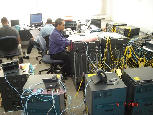
    Cisco 7600, Supervisor 720-3B, MPLS VPN, 10 GE modules, QOS, Cisco 6509, Firewall Blade, NAM, Wireless LWAPP with WISM, OSPF stub, MP-BGP, Cat 4500 Sup V-10GE, XENPAX, IDS blade, ASA with IPS, Cisco 3845 voice gateway, OSPF Stub, MCS 7800, Cisco 6513,
    Routing to the Edges, CSA, Call Manager, Unity, 802.1x, WPA-2, Video Phone, HDV, PVDM2, CiscoWorks, MARS, ACS, Radius, ATM E3, AAA, Layer 3 Roaming, VG224, Load Balancing, Transparent Proxy with WCCP, VTP mode Transparent, Route Target, Port Channel, OSPF Area Authentication, DHCP Option 150, Firewall vlan-group, NTP, High Availability, Dial Peer, Calling Searh Space, BGP Route Reflector, SSHv2, VRF, Call Park, LDAP, 3750 StackWise.
    All in 25 days.